9
ENGLISH
Establish the height of the operator,
bearing in mind that:
• the securing bracket of the
curved arm must be in a zone
where it can be secured to the
gate leaf (Fig.7)
• the minimum off ground height
of the operator must permit
securing the curved arm and
positioning the lower housing (at
least 85mm, see fig.7).
• the lower edge of the rear
bracket must be aligned with
respect to the upper edge of
the front bracket (Fig.8).
Secure the rear bracket in the
position you had established, using
four M8 screws. As you secure the
bracket, respect the lay-out in Fig.
9 and check, using a level, if the
bracket is horizontal.
• To improve water tightness, the external housing covers
the securing bracket - this prevents the bracket from
being directly welded on the pilaster.
• The rear bracket must be secured on an as smooth as
possible surface. For masonry pilasters, a counter-plate
for walling is available as an accessory.
Position the operator on the
bracket you have just secured,
using two M8x100 screws and the
relevant nuts - supplied (Fig.10).
Set the operator for manual
operation, see paragraph 7.
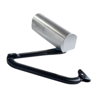
Install the straight arm (Fig.11) with the
supplied screw.
Assemble the rest of the arm as illustrated in Fig.12.
For correct operation, tighten the two securing screws
(Fig.12 ref.) and then loosen them by about 1/2 turn
to enable rotation without any friction on the arms.
Align the arms you have just assembled, pushing in the central
zone until they stop, see Fig. 13 ref. .
There are two stops on the curved arm to facilitate the
aligning operation.
Rest the front bracket on the leaf, Fig.13 ref. .
Move back the front bracket by about 20 mm and mark the
securing holes, Fig. 13 ref. .
Secure the bracket in the established position using two M8
screws.
We advise you to secure the bracket with the screws, and
not weld it to the leaf, in order not to rule out future
adjustments.
Move the bracket by hand and - with the leaf in closing position
- make sure that the two arms do not impact each other, as
shown in Fig. 13 ref. .
Take the operator back to the work position - see paragraph 7.
5.4. WIRING THE OPERATOR
When you have finished securing the operator, you can wire
it. There are three holes in the lower part of the operator. They
should be used for positioning the cable grippers, for routing the
power cables, for connecting accessories and, if necessary, for
connecting the second motor.
Install all the three supplied cable grippers with the securing
nuts (Fig. 14).
• Always use the largest cable gripper (Fig.14 ref.)
• If the other two cable grippers are not used, they must
be closed, using the supplied plugs (Fig.14 ref.). Fit
the plastic plug in the cable routing hole and close the
cable gripper until it is tight.
Connect the power cable, as shown in Fig.15. The earthing wire
must also be connected. Make sure that the power cable wires
are correctly fitted in the 'comb' which restrains them Fig. 15.
• If the protective fuse has to be replaced, use a fuse with
the following characteristics:
5x20 2A 450V
Wire all the accessories and safety devices, observing the
relevant instructions.
FIG. 11
F
IG. 12
F
IG. 13
F
IG. 15
F
IG. 14
FIG. 8
F
IG. 10
FIG. 9
F
IG. 7