18
ENGLISH
ENGLISH
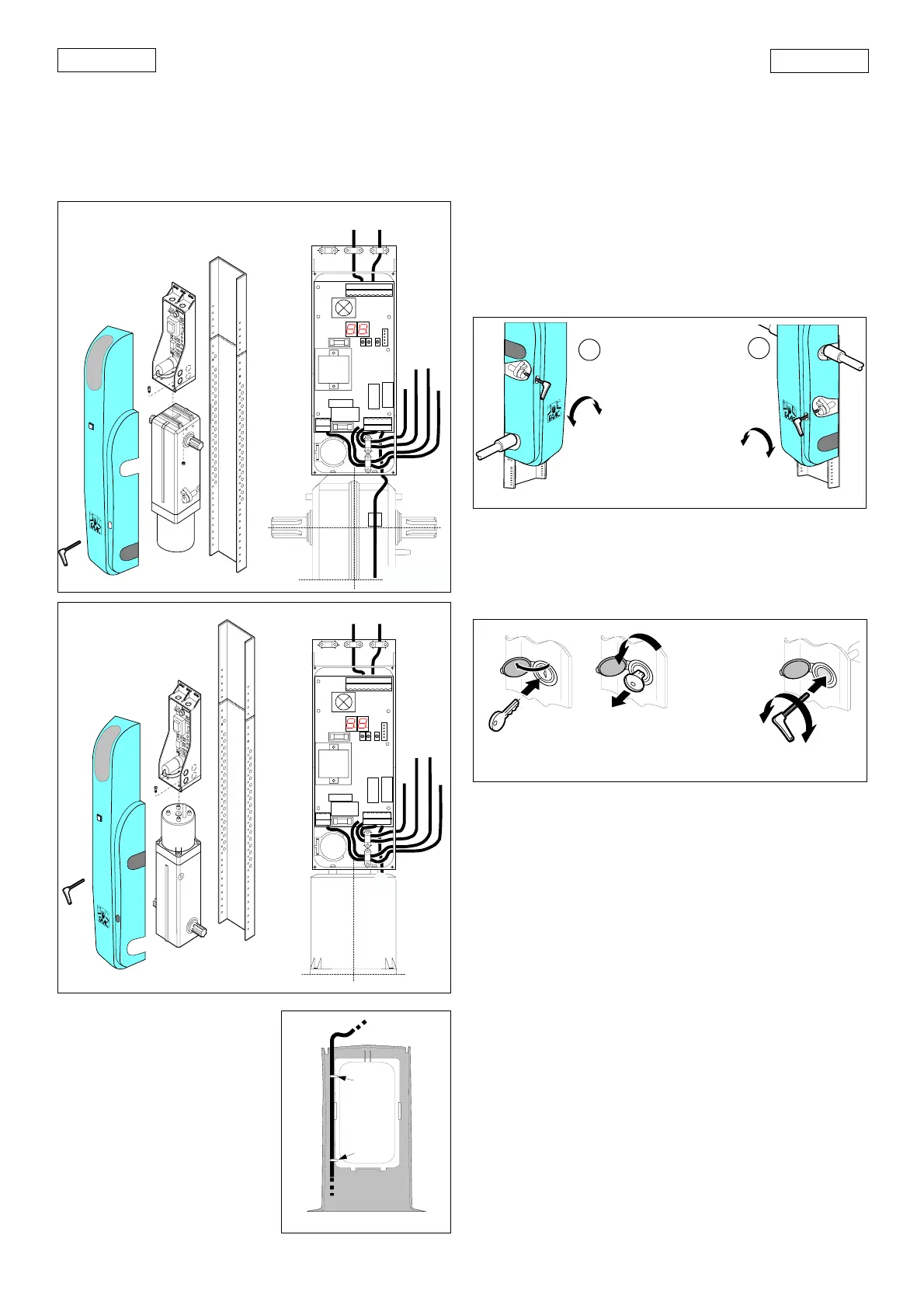
Figs.17-18 also show the recommended layout for routing and fixing
the cables in the card support.
7. MANUAL OPERATION
The operator 550 is equipped with an emergency release device
that can be operated from inside the garage. On request, a lock
can be fitted to the door panel which allows the release device
KEY TO CABLES
햲햲
햲햲
햲 Flashing light
햳햳
햳햳
햳 External courtesy light
햴햴
햴햴
햴 OPEN button on cover
햵햵
햵햵
햵 Low-voltage connections
햶햶
햶햶
햶 550 Slave motor
햷햷
햷햷
햷 230V~ power supply
햸햸
햸햸
햸 550 I motor
Fig. 19
half a turn until the stop is reached.
8. RETURNING TO NORMAL OPERATION
To prevent an accidental movement from activating the door
during the operation, disconnect the power supply from the
system before locking the operator again.
Fig.21
SBLOCCA/UNLOCK
DEBLOQUE/ENTRIEGELT
DESBLOQUEAR
BLOCCA/LOCK
BLOQUE/VERRIEGELT
BLOQUEAR
- From inside (Fig.20)
Insert the hex wrench provided and turn anticlockwise about
half a turn until the stop is reached.
Note:depending on the type of installation, the release device
may be on the right (A) or the left (B).
- From outside (Fig.21)
1) Insert the hex wrench provided and turn clockwise about half
a turn until the stop is reached.
2) Remove the hex wrench and insert the lock unit.
3) Turn the wrench clockwise so that it can be removed; close
the safety door again.
9. MAINTENANCE
Carry out the following operations at least every six months:
•Check that the motor torque is set correctly.
•Check the door’s rollers and sliding guides; clean and
lubricate if necessary.
• Check the efficiency of the release system.
•Check the efficiency of the safety devices.
10.REPAIRS
For repairs contact authorised FAAC Service Centres.
Fig. 20
BLOCCA/LOCK
BLOQUE/VERRIEGELT
BLOQUEAR
SBLOCCA/UNLOCK
DEBLOQUE/ENTRIEGELT
DESBLOQUEAR
SBLOCCA/UNLOCK
DEBLOQUE/ENTRIEGELT
DESBLOQUEAR
BLOCCA/LOCK
BLOQUE/VERRIEGELT
BLOQUEAR
A
B
to be operated also from outside the garage.
If the door has to be operated manually due to a power failure
or a malfunction of the automation system, operate the release
device as follows:
- From inside (Fig. 20)
Insert the hex wrench provided and turn clockwise about half a
turn until the stop is reached.
Warning:depending on the type of installation, the release
device may be on the right (A) or left (B).
- From outside (Fig.21)
1) Open the safety door and insert the wrench.
2) Turn anticlockwise as far as possible and remove the lock unit.
3) Insert the hex wrench provided and turn anticlockwise about
햷
12345678910
11 12
13
14
15
16
PE
NL
J3
J5
J4
J2
J1
+
-F
FCA
OPEN
FCC
FSWOP
STOP
FSWCL
F2
F1
TF1
햳
햴햵
햶
햷
햸
Fig. 17
햲
12345678910
11 12
13
14
15
16
PE
NL
J3
J5
J4
J2
J1
+
-
F
FCA
OPEN
FCC
FSWOP
STOP
FSWCL
F2
F1
TF1
햳
햴햵
햶
햷
Fig. 18
햸
햲