12
ENGLISH
ENGLISH
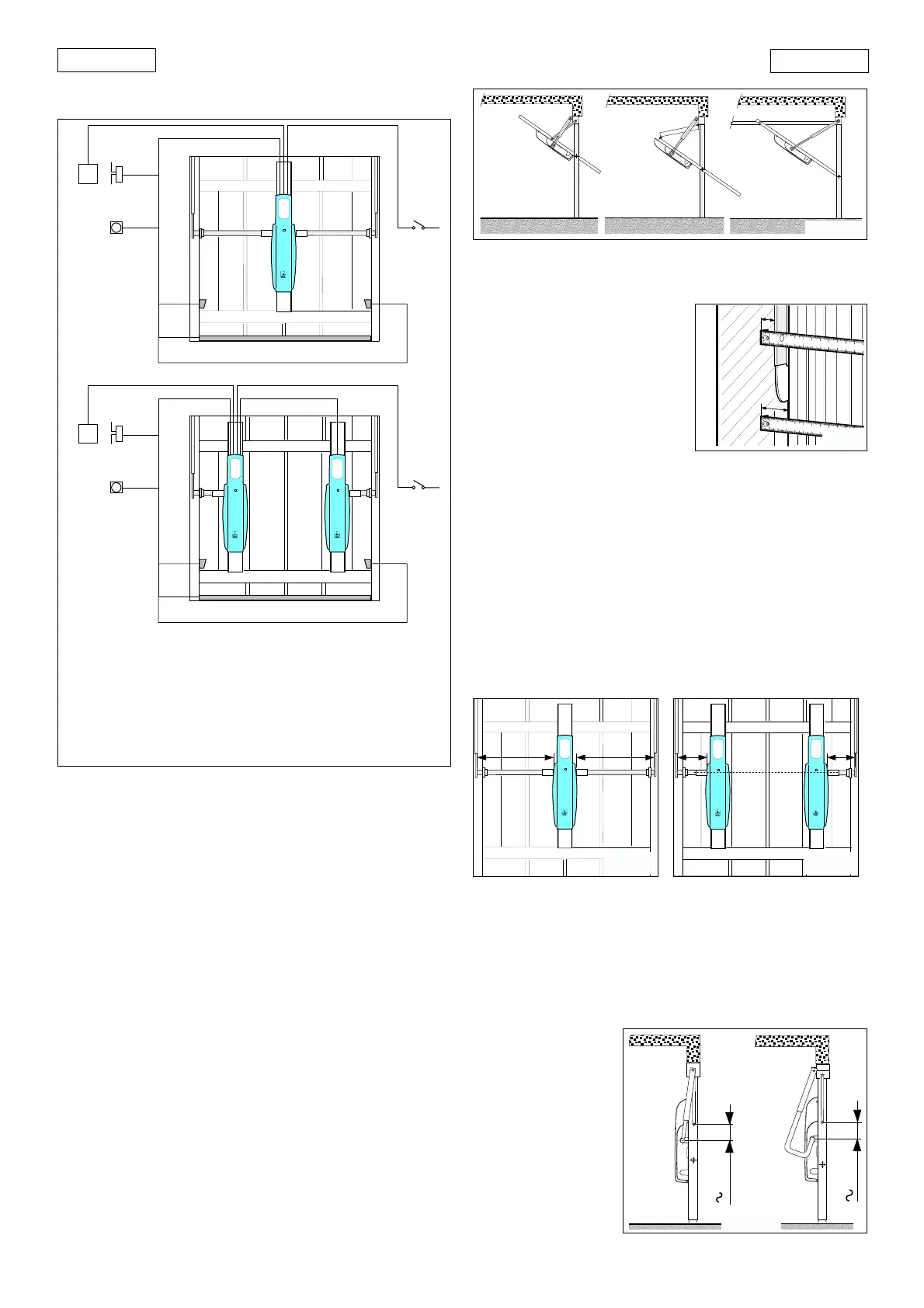
3. ELECTRICAL INSTALLATION LAYOUT (standard system)
햲햲
햲햲
햲 550 I operator with 550MPD control unit
햳햳
햳햳
햳 550 Slave operator
햴햴
햴햴
햴 Flashing light
햵햵
햵햵
햵 Radio receiver
햶햶
햶햶
햶 Keyswitch
햷햷
햷햷
햷 Photocells
햸햸
햸햸
햸 Safety edge
햲햳
햴햵
햶
햷
햸
햷
햲
햴햵
햶
햷
햸
햷
4. INSTALLING THE AUTOMATION SYSTEM
4.1. PRELIMINARY CHECKS
To ensure safe, proper operation of the automation system,
check the following:
• The door’s structure must be suitable for automation.
Make particularly sure that dimensions of the door meet
the requirements given in the technical specifications and
that the door is sufficiently robust.
• Check the condition of the door bearings and joints.
• Check that the door moves smoothly. If necessary clean
the tracks and lubricate them with a silicone based lubri-
cant. Do not use grease.
• Check that the door is correctly balanced.
• Remove the mechanical door locks so that when the door
is closed it is locked only by the automation system.
• Check that there is an effective earth connection for the
geared motor.
The 550 automation system is designed to operate various
types of counterbalanced up-and-over garage doors. Fig. 4
shows the most common types:
햲 single section outward swinging
햳 double section outward swinging
햴 single section inward swinging with horizontal tracks
4.2. POSITIONING TELESCOPIC ARMS
The gap between the existing
balancing arm and the frame
(distance ”S1” in Fig. 5) must be at
least 15 mm to allow the straight
telescopic arms to rotate correctly.
If not, it is possible to use curved
telescopic arms which can be
installed over the top of existing
balancing arms. Check that the
gap between the door panel and
the frame is at least 20 mm
(distance ”S2” in Fig. 5).
4.3. POSITIONING OPERATOR/BACK PLATE
In accordance with the measurements given in Table 1, install
either a single operator (550 I) at the centre of the door as shown
in Fig. 6 or two operators (one 550 I and one 550 Slave) at the sides
of the door as shown in Fig. 7.
The operator 550 is designed so that the geared motor unit can
be installed with the drive shaft at two different heights (see
section 6).
The following instructions apply to both assembly options,
although they refer specifically to installation of the operator with
the geared motor unit as it is delivered from the factory.
Fig. 3
4.4. ASSEMBLY SEQUENCE
Begin installation with the garage door closed and the operator
released (see chapter 7).
1) Determine the position of the operator shaft as follows:
• single section outward swinging garage door (Fig. 8)
When the door is closed, the axis of rotation of the drive shaft must
be about 10 cm lower than the axis of rotation of the door. The
telescopic arms must be
attached as close as
possible to the point
where the door arm is
fixed.
10 cm
10 cm
Fig.8
==
==
Fig. 6 Fig. 7
햲햴햳
Fig. 4
S1
S2
2x0.5 4x0.5
2x0.5
3x0.5
3x0.5
2x1.5
2x1.5 +
9
5x1.5 +
9
2x1.5
3x0.5
3x0.5
2x0.5
2x0.5
4x0.5
•The cable cross-sections are expressed in mm
2
Fig. 5
2x1.5 +
9