1
INDEX
1. ..WARNINGS ..................................................................................................................................................3
2. ..TECHNICAL SPECIFICATIONS .......................................................................................................................3
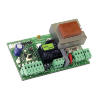
3. ..LAYOUT AND COMPONENTS OF 624BLD .....................................................................................................3
3.1 Description of components ..................................................................................................................3
4. ..ELECTRICAL CONNECTIONS ........................................................................................................................4
4.1 J1 Terminal-board - Accessories (Fig. 2) ...........................................................................................4
4.2 Connection of relay photocells and safety devices with “N.C.” contact ............................................... 5
4.3 Connection of BUS photocells ............................................................................................................5
4.4 J2 Terminal-board - Motor, flashing lamp and fan (Fig. 2) ...............................................................6
4.5 J8 Connector - Motor capacitor (Fig. 2) ............................................................................................6
4.6 J9 Terminal-board - Power supply (Fig. 2) ..........................................................................................6
4.7 J3, J5 Rapid connectors - for opening and closing limit-switches (Fig. 2) .........................................6
4.8 J6 Connector - Beam breaking sensor (Fig. 2) ....................................................................................6
4.9 DS1 Frequency selector (Fig. 1) ...................................................................................................................... 6
4.10
J4 Connector - for Minidec, Decoder and RP ............................................................................................. 6
5. ..PROGRAMMING ..........................................................................................................................................6
5.1 1st LEVEL PROGRAMMING ...................................................................................................................6
5.2 Modification of the pre-setting .........................................................................................................8
5.3 Setup and BUS system control ........................................................................................................................ 8
5.4 2nd LEVEL PROGRAMMING ................................................................................................................. 9
5.5 Setup for integrated Loop Detector .................................................................................................10
6. ..START-UP ...................................................................................................................................................... 11
6.1 Board LEDS check ...............................................................................................................................11
6.2 Check on BUS status ...........................................................................................................................11
7. ..AUTOMATED SYSTEM TEST ............................................................................................................................11
8. ..MASTER-SLAVE CONFIGURATIONS ...............................................................................................................12
9. ..3rd LEVEL PROGRAMMING ..........................................................................................................................13
9.1 Customisation of function logic..........................................................................................................15
10. PRE-SETTING VALUES ...................................................................................................................................15
11. NOTES .........................................................................................................................................................16
12. INTERLOCK CONNECTION ...........................................................................................................................16
13. FUNCTION LOGIC TABLES ............................................................................................................................17
ENGLISH