4
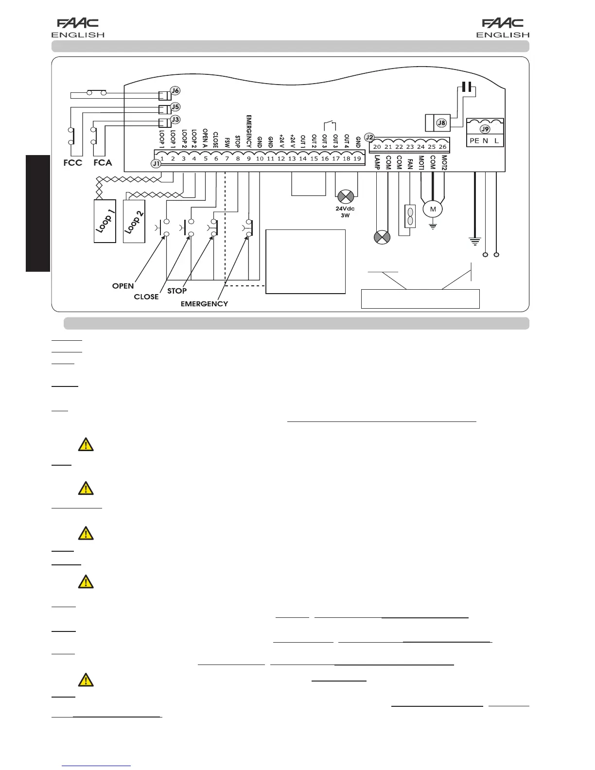
4. ELECTRICAL CONNECTIONS
To connect the
photocells and
safety devices,
consult paragraph
4.2.
BLUE
MOTOR THRUST
CAPACITOR
FAN
MOTOR
BEAM
BREAKER
Fig. 2
LOOP 1 - Magnetic loop LOOP 1 (OPEN - terminals 1-2): it activates the OPENING function
LOOP 2 - Magnetic loop LOOP 2 (SAFETY/CLOSE - terminals 3-4): it activates the SAFETY/CLOSING function
OPEN - “Opening” Command (N.O. - terminal 5): this refers to any pulse generator ( e.g.: push-button) which, by closing
a contact, commands the barrier to close and/or open.
CLOSE - “Closing” Command (N.O. - terminal 6): this refers to any pulse generator (e.g.: push-button) which, by closing
a contact, commands the barrier to close.
FSW - Closing safety-devices contact (N.C. - terminal 7). The purpose of the closing safety devices is to protect the
barrier movement area during closure, by reversing motion. They are never tripped during the opening cycle. If the closing
Safety devices are engaged when the automated system is in open status, they prevent the closing movement.
If closing safety devices are not connected, jumper connect the FSW and GND terminals (fig. 6).
STOP - STOP contact (N.C. - terminal 8): this refers to any device (e.g.: push-button) which, by opening a contact, can
stop the motion of the automated system.
If stop safety devices are not connected, jumper connect the STOP and GND terminals (fig. 6).
EMERGENCY - EMERGENCY contact (N.C- terminal 9): this refers to any switch which, by being activated in emergency
state, opens the barrier and stops its movement until the contact is restored
.
If emergency safety devices are not connected, jumper connect the EMERGENCY and GND terminals (fig. 6).
GND ( terminals 10-11-19) - Negative contact for feeding accessories
24 Vdc ( terminals 12-13)- Positive contact for feeding accessories
Max. load of accessories: 500 mA. To calculate absorption values, refer to the instructions for individual
accessories
OUT 1 - Output 1 GND open-collector (terminal 14): The output can be set in one of the functions described in the
2nd programming level (see par. 5.2.). Default value is FAILSAFE. Maximum load: 24 Vdc with 100 mA.
OUT 2 - Output 2 GND open-collector (terminal 15): The output can be set in one of the functions described in the
2nd programming level(see par. 5.2.). Default value is CLOSED beam. Maximum load: 24 Vdc with 100 mA.
OUT 3 - RELAY Output 3 (terminal 16-17): The output can be set in one of the functions described in the 2nd programming
level (see par. 5.2.). Default value is INDICATOR LIGHT: Maximum load: 24 Vdc or Vac with 500 mA.
To avoid endangering correct operation of the system, do not exceed the indicated power indicated in fig. 2.
OUT 4 - Output 4 open-collector +24Vdc (terminal 18): The output can be set in one of the functions described in the
2nd programming level (see par. 5.2.). The default value for ALL THE PRE-SETTINGS is BUS COMMUNICATION. Maximum
load: 24 Vdc with 100 mA.
4.1. J1 TERMINAL-BOARD - ACCESSORIES (FIG. 2)
230 V~
or 115 V~
60W max
*
230 V~
or 115 V~
50/60 Hz
*
* 230 V~ board version
or 115 V~ board version
ENGLISH