3
1. WARNINGS
Attention: Before attempting any work on the control unit (connections, maintenance), always turn off power.
- Install, upstream of the system, a differential thermal breaker with adequate tripping threshold.
- Connect the earth cable to the terminal on the J9 connector of the unit (see fig.2).
- Always separate power cables from control and safety cables (push-button, receiver, photocells, etc.). To avoid any electrical
noise, use separate sheaths or a screened cable (with the screen earthed)
.
CONTROL UNIT 624 BLD
3. LAYOUT AND COMPONENTS OF 624BLD
Power supply
voltage *
230 V
~
(+6% -10%) - 50/60 Hz
or
115 V
~
(+6% -10%) - 50/60 Hz
Absorbed power
7 W
Motor max. load
300 W
Power supply
for accessories
24 Vdc
Accessories max.
current
500 mA
Operating ambient
temperature
from -20°C to +55°C
Protection
fuses *
F1 = F 5A - 250V F2 = T 0,8A - 250V
or
F1 = F 10A - 120V F2 = T 0,8A - 120V
Work time
Programmable (from 0 to 4 minutes)
Pause time
Programmable (from 0 to 4 minutes)
Motor power
Programmable on 50 levels
Programming
3 programming levels for greater
flexibility of use
Rapid connector
Coupling for 5-pin Minidec board,
Decoder, Receiver RP/RP2
Programmable
outputs
4 programmable outputs
in 18 different functions
Features
Management of slow-downs,
multifunction display, BUS technology
and INTEGRATED METALLIC MASS
DETECTOR
* The power supply voltage and fuses depend on the version
purchased
2. TECHNICAL SPECIFICATIONS
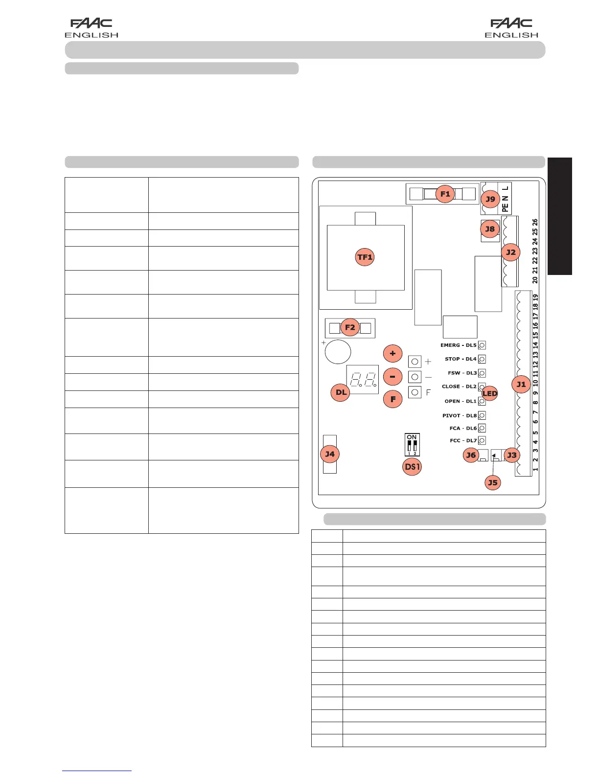
3.1 DESCRIPTION OF COMPONENTS
DL SIGNALS AND PROGRAMMING DISPLAY
LED INPUT STATUS CONTROL LEDs
J1 LOW-VOLTAGE TERMINAL BOARD
J2
TERMINAL BOARD FOR CONNECTION OF MOTOR, FLASHING
LAMP AND FAN
J3 OPENING LIMIT-SWITCH CONNECTOR
J4 CONNECTOR FOR DECODER MINIDEC / RP RECEIVER
J5 CLOSING LIMIT-SWITCH CONNECTOR
J6 CONNECTOR FOR ROD BREAKING SENSOR
J8 CONNECTOR FOR MOTOR THRUST CAPACITOR
J9 TERMINAL-BOARD FOR 230 VAC POWER SUPPLY
DS1 LOOP 1 and LOOP 2 FREQUENCIES SELECTOR
F1
FUSE FOR MOTORS AND TRANSFORMER PRIMARY WINDING (F 5A)
F2 FUSE FOR LOW VOLTAGE AND ACCESSORIES (T 800mA)
F PROGRAMMING PUSH-BUTTON “F”
+ PROGRAMMING PUSH-BUTTON “+”
- PROGRAMMING PUSH-BUTTON “-”
TF1 TRANSFORMER
Fig. 1
ENGLISH