24
–
+
DL
Led
F1
J1
J2
Led
J5
F
J7
F2
J8
J6
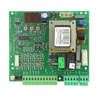
Fig. 22
DL SIGNALLING AND PROGRAMMING DISPLAY
Led INPUTS STATUS CONTROL LED
J1 LOW VOLTAGE TERMINAL BOARD
J2 CONNECTOR FOR DECODER/MINIDEC/RP RECEIVER
J5 CONNECTOR FOR MOTOR STARTING CAPACITOR
J6 MOTOR AND FLASHING LAMP CONNECTION TERMINAL BOARD
J7 230 Vac POWER SUPPLY TERMINAL BOARD
J8 DOUBLE CONNECTOR - RAPID CONNECTION TO LIMIT-SWITCH
F1 MOTOR AND TRANSFORMER PRIMARY WINDING FUSE (F 5A)
F2 LOW VOLTAGE AND ACCESSORIES FUSE (T 800mA)
F "F" PROGRAMMING PUSH-BUTTON
– "–" PROGRAMMING PUSH-BUTTON
+ "+" PROGRAMMING PUSH-BUTTON
1 OPEN A (total opening)
2 OPEN B (partial opening)
3 FSW-OP (opening safety devices)
4 FSW-CL (closing safety devices)
5 STOP
6 SAFE (“edge” safety devices)
7 - (negative for power supply to accessories)
8 - (negative for power supply to accessories)
9 +24V (supply to accessories)
10 +24V (supply to accessories)
11 FSW-TX (negative for emitting photocells - FAILSAFE)
12 W.L. (negative for indicator light)
J1 CONNECTOR
Power supply V~ (+6% -10%) 230
Absorbed power (W) 10
Motor max. load (W) 1000
Accessories max. load (A) 0,5
Operating ambient temperature -20 °C +55 °C
Protection fuses 2 (see fig. 22 and par. 5.3)
Function logics: Automatic / “Stepped” automatic / Semi-automatic / Safety
devices / Semi-automatic B / Dead-man C / “Stepped” semi-automatic /
Mixed B/C logic
Work time Programmable (from 0 to 4,1 min.)
Pause time Programmable (from 0 to 4,1 min.)
Thrust force Adjustable over 50 levels
Terminal board inputs: Open - Partial Open - Opening safety devices - Closing
safety devices - Stop - Edge - Power supply+Earth
On-connector inputs Opening and closing limit-switch -
Motor capacitor
Terminal board outputs: Flashing lamp - Motor - 24 Vdc accessories power
supply- 24 Vdc indicator-light / Timed output / Electric lock command - 'traffic
lights' - Failsafe
Rapid connector 5-pin card connection for Minidec, Decoder or RP receivers
Programming 3 keys (+, -, F) and display, "basic" or "advanced" mode
Basic mode programmable functions: Function logic - Pause time - Thrust Force
- Opening-closing direction
Advanced mode programmable functions: Torque at initial thrust - Braking - Fail
safe- Pre-flashing - Indicator-light/Timed output/Electric lock or 'traffic lights'
command -Opening and closing safety devices logic - Encoder/ Anti-crushing
sensitivity -Decelerations - Partial opening time - Work time - Assistance request
- Cycle counter
5.2. TECHNICAL SPECIFICATIONS
5.1. WARNINGS
Important: Before attempting any work on the control board
(connections, maintenance), always turn off power.
- Install, upstream of the system, a differential thermal breaker with
adequate tripping threshold.
- Connect the earth cable to the terminal on J7 connector of the
board, and to the bush on the operator (figs. 22 and 40).
- Always separate power cables from control and safety cables
(push-button, receiver, photocells, etc.). To avoid any electric
noise, use separate sheaths or a shielded cable (with earthed
shield).
5. CONTROL BOARD 780D
5.3. LAYOUT AND COMPONENTS