DL1
DL3
DL2
DL3
DL2
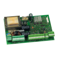
Connection of the BUS input to the control board is via the
bipolar cables which come out of the encoders.
Unlike the case of the photocell devices, the polarity of
the BUS line connection determines whether the encoder
is associated with one leaf rather than with the other.
This is why you must pay great attention to the indications of
the status LEDs on the body of each encoder (Fig.1).
Below we list the functions of LEDs LD1, DL2, and DL3, and their
statuses:
TAB. 1 - Encoder connection and LED status
LED ON FLASHING OFF
DL 1
Power ON
and BUS
communicating
with board
Power ON
but BUS not
communicating
No Power or BUS
communication
DL 2 Leaf 1 encoder
-- Leaf 2 encoder
DL 3
--
Pulses read
while leaf
moving
--
11 S700H/S800H: BUS ENCODER WIRING
DL1 must always be ON to guarantee a correct
connection between encoder and board.
DL 2 identifies leaf 1 and leaf 2.
If correctly configured, the encoder boards are as follows:
DL2 ON for leaf 1.
DL2 OFF for leaf 2.
In the event of an incorrect connection, i.e. two encoders have
the DL2 LEDs with the same status, during the BUS accessory
learning procedure, the DL1 LEDs of both encoders will flash.
In this condition, please refer to the configuration on the table
in order to determine which encoder connection needs to be
reversed.
DL3 indicates, by means of a regular flashing, the reading of
the impulses during the movement of the leaf.
If the leaf is at rest, DL 3 can be both ON and OFF
N.B. in particular motionless leaf positions, DL3 may flutter
considerably. This signal must not be considered a fault.
LEAF 1 LEAF 2
LEAF 2 LEAF 1
OFF
ON
ON
OFF
10 AUTOMATED SYSTEM TEST
When you have finished programming, check if the system is
operating correctly. In particular, check if the safety devices
are operating correctly.
Fig. 6
Fig. 7
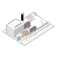
9.1 BATTERY KIT OF E024S ON 391 (OPTIONAL)
The battery kit enables you to activate the automated system
even in the event of a mains power fault. The batteries are
housed in a specific compartment inside the operator (see
sequence in fig. 6).
To install, refer to the specific instructions.
The batteries start operating when mains
voltage fails.
ENGLISH
11