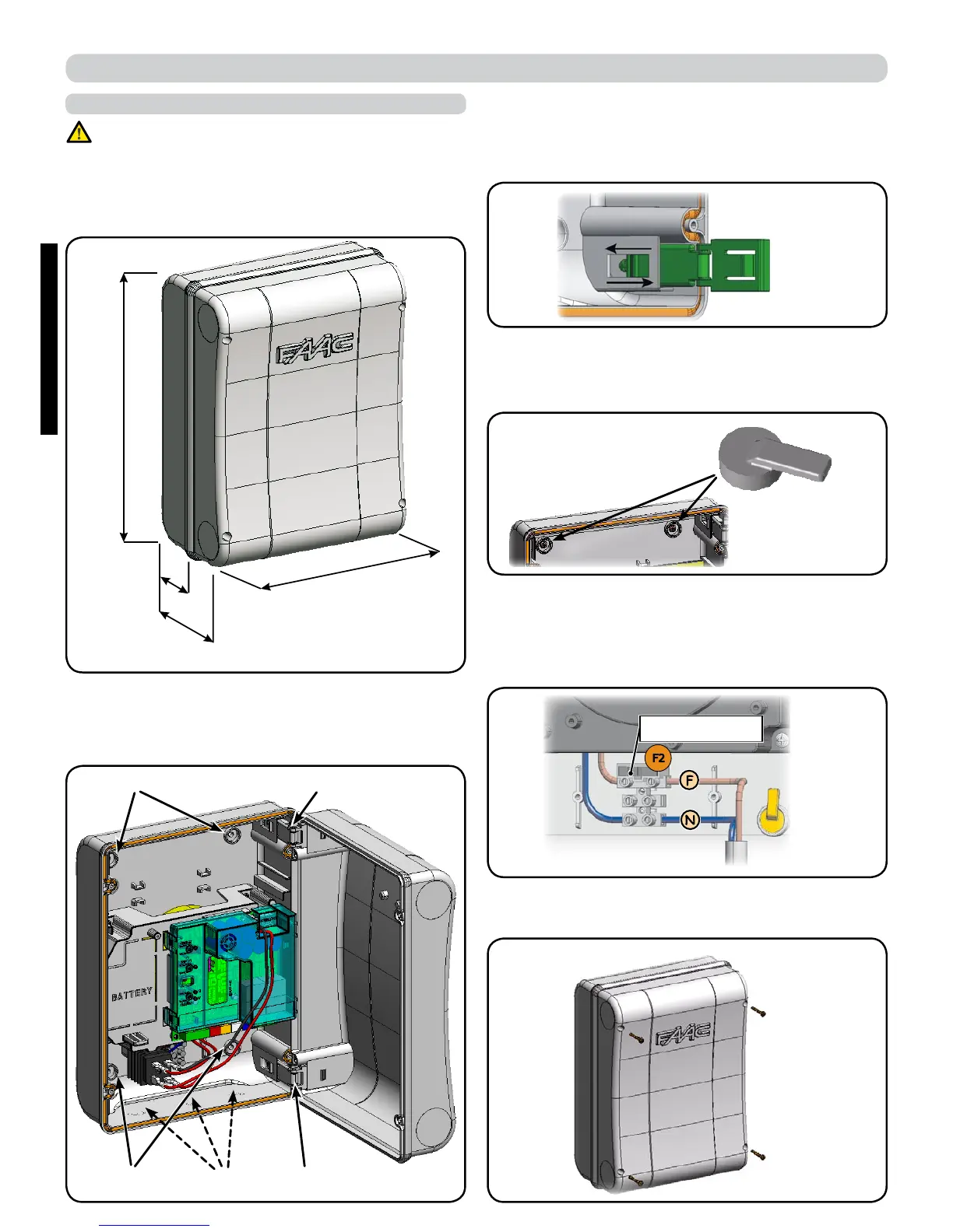
306
225
Fig. B
Fig. F
Fig. C
Fig. D
Fig. E
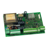
230V -> 2,5A - 250V
115V -> 4A - 120V
Fig. A
130
64
0 BOX LAYOUT
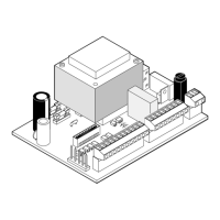
Fig. B shows the four 5 mm diam. holes for securing the box (ref.
) to the wall, the three facilities for istalling the cable grippers
M16/M20/M25 (ref.) and the two cover hinges (ref.).
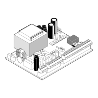
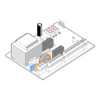
THE BOX CONTAINS THE E024S CONTROL UNIT AND THE
DEVICES TO POWER IT. IT MUST THEREFORE BE HANDLED
WITH CARE DURING ALL INSTALLATION STAGES, TO AVOID
DAMAGING ITS COMPONENTS.
The dimensions of the box are shown in Fig.A:
The cover hinges can be moved upward to allow opening the
box housing (Fig. C); they can also be removed and re-positio
-
ned in order to enable the cover to open to the right or left.
When you have secured the box in the selected position, cover
the securing holes (ref.
Fig.B) and the screws with the supplied
plugs as shown in Fig.D.
Connect the power cable as shown in Fig.E.
After having connected the control board to the different parts
of the automated system, close the box by placing the cover
on its seat with gasket.
Dimensions in mm
ELECTRICAL BOX E024S
Next, tighten the four supplied screws to guarantee the degree
of protection against external agents (Fig.F).
ENGLISH
2