WARNINGS
• Important! For the safety of people, it is important that all the instructions be carefully observed.
• Incorrect installation or incorrect use of the product could cause serious harm to people.
• Carefully read the instructions before beginning to install the product and keep them for future
reference.
• The symbol indicates notes that are important for the safety of persons and for the good condition
of the automated system.
• The symbol draws your attention to the notes on the characteristics and operation of the product.
CE DECLARATION OF CONFORMITY
Manufacturer: FAAC S.p.A.
Address: Via Calari, 10 - 40069 Zola Predosa BOLOGNA - ITALY
Declares that: Control board mod. E024S,
• conforms to the essential safety requirements of the following EEC directives:
2006/95/EC Low Voltage Directive
2004/108/EC Electromagnetic Compatibility Directive
Additional information:
This product underwent a test in a typical, uniform configuration.
(all products made by FAAC S.p.A)
Bologna 20-04-2010 The Managing Director
A. Marcellan
INDEX
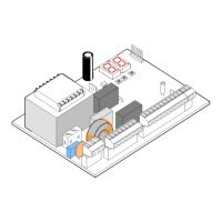
0 BOX LAYOUT .....................................................................................................................................2
1 WARNINGS .......................................................................................................................................3
2 LAYOUT AND CONNECTION
S ............................................................................................................3
3 TECHNICAL SPECIFICATIONS
...........................................................................................................4
3.1 DESCRIPTION OF COMPONENTS ........................................................................................................ 4
3.2 DESCRIPTION OF TERMINAL-BOARDS .................................................................................................
4
3.3 ANTI-CRUSHING FUNCTION .................................................................................................. 4
4 PROGRAMMING THE LOGIC .............................................................................................................4
5 PROGRAMMING THE SPEED ..............................................................................................................4
6. START-UP ...........................................................................................................................................5
6.1 LEDS CHECK...................................................................................................................................... 5
6.2 PROGRAMMING THE DIP-SWITCHES ................................................................................................... 5
6.3 TIME LEARNING – SETUP ....................................................................................................................
5
6.3.1 AUTOMATIC SET-UP ................................................................................................................................................5
6.3.2 MANUAL SET-UP .....................................................................................................................................................5
6.3.3 PROGRAMMING THE LOGIC ..................................................................................................................................6
6.3.4 SECOND LEVEL PROGRAMMING - ADVANCED FUNCTIONS ....................................................................................6
7 INSTALLATION OF BUS ACCESSORIES ................................................................................................7
7.1 SETTING THE BUS PHOTOCELLS .......................................................................................................... 7
7.2 MEMORY STORAGE OF BUS ACCESSORIES .......................................................................................
8
8 MEMORY STORING THE RADIO CODE ...............................................................................................8
8.1 MEMORY STORAGE OF DS RADIO CONTROLS ................................................................................... 8
8.2 MEMORY STORAGE OF SLH RADIO CONTROLS
.................................................................................. 8
8.3 MEMORY STORAGE OF RC/LC RADIO CONTROLS .............................................................................. 9
8.3.1 REMOTE MEMORY STORAGE OF RC/LC RADIO CONTROLS ............................................9
8.4 RADIO CONTROLS DELETION PROCEDURE ........................................................................................ 9
9 CONNECTION OF BUFFER BATTERIES (OPTIONAL) ..............................................................................9
10 AUTOMATED SYSTEM TEST .................................................................................................................
9
11 S700H/S800H: BUS ENCODER WIRING
............................................................................................
11
12 S450H BUS ENCODER WIRING.......................................................................................................12
13 LOGIC TABLES .................................................................................................................................12
ENGLISH
1