3 TECHNICAL SPECIFICATIONS
Power supply voltage
*
230V~ (+6% -10%) - 50Hz
or
115V~ (+6% -10%) - 60Hz
Absorbed power
4W
Motor max. load
150W x 2
Accessories max. current
(+24V=)
250 mA
BUS Accessories max.current
400 mA
Operating ambient tempera-
ture
-20°C... +55°C
Fuses
*
F1 = self-resetting;
F2 = T2A-250V~
or T4A-
120V~
Function logics
A, E, AP, EP,A1,B,C
Work time (time-out)
5 minutes (fixed)
Pause time
Varies according to learning
(max. 10 min.)
Terminal board inputs
Open A, Open B, Stop, BUS
(I/O)
Connector inputs
Power supply, battery
module XF 433 or XF 868
Terminal board outputs
Motors, flashing lamp, power
supply to accessories,
electric lock, service light
contact (90 sec fixed)
Programmable functions
Speed (High - Low)
Learning functions
Pause time,
leaf closing delay
Integrated radio channels
type
DS, SLH (max 250 channels)
LC -RC (max 250 channels )
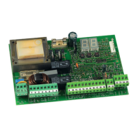
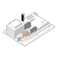
J1 POWER SUPPLY connector
J2
SERVICE LIGHT command terminal-board
J3 FLASHING LAMP terminal-board
J4 ELECTRIC LOCK terminal-board
J5 COMMANDS terminal-board
J7 MOTOR 1 terminal-board
J8 MOTOR 2 terminal-board
J9 Rapid connection for XF MODULE
J10 BUS terminal-board
J11 BATTERY connector
SW1 SET UP push-button
SW2 SPEED push-button
SW3 LOGIC push-button
DS1 Programming Dip-switch
F1 Accessories protective fuse
F2 Fuses protecting transformers and motors
LED Signalling LEDs
3.1 DESCRIPTION OF COMPONENTS
Terminal and/or
terminal-board
Description Device connected
1
J5
+24V=
Power supply for
accessories
2 GND Negative
3 STOP
Device with NC
contact which causes
the automated
system to shut down
4 OPEN B
Device with N.O
contact (see chap.
FUNCTION LOGICS)
5 OPEN A
J10
RED terminal
BUS
Safety devices with
BUS technology
J2
GREY terminal
SERVICE
LIGHT
Service Light control
output (connect a
relay coil at 24V=
/100mA max)
J3
ORANGE terminal
LAMP
Flashing lamp 24V=
/ 15W
J4
BLUE terminal
LOCK
Electric lock 12V~ or
24 V= (to be installed
on leaf 1)
J7 MOT1 Motor 1 (leaf 1)
J8 MOT2 Motor 2 (leaf 2)
3.2 DESCRIPTION OF TERMINAL-BOARDS
5 PROGRAMMING THE SPEED
The function SPEED can be adjusted at any time by pressing
push-button SW2.
The selected speed is then displayed on LED LD8:
LED on = HIGH speed
LED off = LOW speed
Leaf 1 means the leaf which opens first during
the opening operation.
The service light control is active during the
entire gate opening or closing movement and
for the successive 90 seconds.
* The power supply and the fuse are related to the purchased
version. The self-resetting fuse F1 stops the power supply to the
accessories by opening a circuit if a current over 500 mA is
detected. It automatically resets after 5 seconds.
3.3 ANTI-CRUSHING FUNCTION
The electronic anti-crushing function is obtained by controlling
the current consumption or the encoder of the motors
connected to the E024S unit.
If the gate detects an obstacle during the opening or closing
movement, the anti-crushing function activates and reverses
the sense of direction of the operator, thus increasing the safety
degree of the automated system.
4 PROGRAMMING THE LOGIC
Repeatedly press the SW3 LOGIC push-button to select one of
the 7 programming logics available.
The selected logic is signaled by the LD7 LED: the number of
flashings corresponds to the number of the selected logic.
See paragraph 6.3.3.
ENGLISH
5