E024S 11 732642 - Rev. F
a
a
8 MEMORY STORING THE RADIO CODE
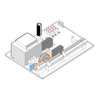
Thecontrolunithasanintegrated2-channeldecodingsystem
(DS,SLH,LC)namedOMNIDEC.Thissystemmakesitpossibleto
memory-storebothtotalopening(OPENA)andpartialopening
OPENB)oftheautomatedsystem-thisismadepossibleby
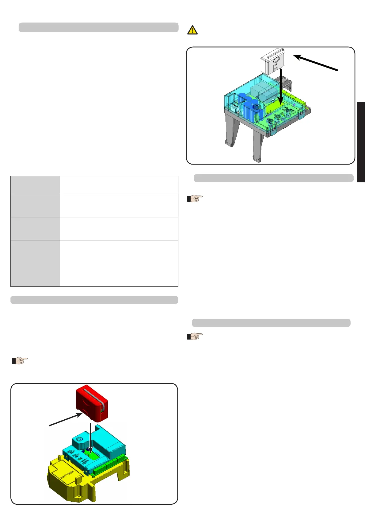
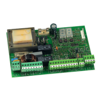
anadditionalreceivermodule(fig.3Aref.a)andFig.3Bref.1
forE024Sfor391)andradiocontrolsonthesamefrequency.
The 3 types of radio codes (DS, LSH, RC) cannot
coexist.
Only one radio code can be used at a time.
8.1
MEMORY STORAGE OF DS RADIO CONTROLS
A maximum of two codes can be stored. One
on the OPEN A channel and one on the OPEN B
channel.
1. On the DS radio control, select the required ON-OFF
combinationforthe12dip-switches.
2. PresstheLOGIC(SW3)orSPEED(SW2)push-button,tomemory
storerespectivelytotalopening(OPENA)orpartialopening
(OPENB),andasyouholditdown,alsopresstheSETUP(SW1)
push-button.TherelevantLEDstartstoflashslowlyfor5sec.
3. Releasebothpush-buttons.
4. Withinthese5sec.,presstheappropriatepush-buttononthe
radiocontrol.
5. TherelevantLEDlightsuponsteadybeamfor1secondand
thengoesOFF,indicatingthatstoragewasexecuted.
6. Toaddotherradiocontrols,setthesameON-OFFcombination
usedinpoint1.
8.2
MEMORY STORAGE OF SLH-SLH LR RADIO CONTROLS
A maximum of 250 codes can be memory
stored, split between OPEN A and OPEN B.
1. OntheSLHradiocontrol,simultaneouslypressandholddown
push-buttonsP1andP2.
2. TheradiocontrolLEDbeginstoflash.
3. Releasebothpush-buttons.
4. Within5s,whiletheradiocontrolLEDisstillflashing,pressand
holddowntheselectedpush-buttonontheradiocontrol
(theradiocontrolLEDlightsonwithsteadybeam).
5. Press the LOGIC (SW3) or SPEED (SW2) push-button to
respectively memory store total opening (OPEN A) or
partialopening(OPENB)and,byholdingitdown,pressthe
push-buttonSETUP(SW1
6. TheLEDontheboardlightsuponsteadybeamfor1second
andthengoesOFF,indicatingthatstoragewasexecuted.
7. Releasetheradiocontrolpush-button.
8. Quicklypresstwicethememorystoredradiocontrolpush-
button.
The automated system performs one opening
operation. Make sure that the automated
7.2 MEMORY STORAGE OF BUS ACCESSORIES
ItispossibletoaddBUSaccessoriestothesystematanytime
bysimplysavingthemontheboard,inthefollowingmanner:
1. Install and program the accessories using the required
address(seeparagraph7.1)
2. Cutpowertotheboard.
3. Connectthetwoaccessoriescablestotheredterminal-board
J10(anypolaritywilldo).
4. Poweruptheboard,takingcaretofirstconnectthemainpower
supply(transformeroutput)andthenanybatteriesandwait
fortheBUSLEDtolighton.
5. QuicklypressonceonlytheSW1(SETUP)push-button,toexecute
learning.TheBUSLEDflashes.
6. GiveanOPENimpulse,leaveswillmoveandtheBUSlearning
procedureisover.
TheboardhasmemorystoredtheBUSaccessories.Followthe
instructionsinthetablebelowtocheckiftheBUSconnection
iscorrect.
Tab. 4 - Description of BUS LED
Steady light
Normal operation (LED ON even in the
absenceofphotocells)
Slow flashing
lamp (flash
every0.5sec)
At least one input engaged: photocell
engagedornotaligned,OpenAorOpen
BorStopinputengaged
Light OFF
(flashevery2.5
sec)
BUSlineshortcircuited
Fast flashing
lamp (flash
every0.2sec)
If you have detected a BUS connection
error,repeattheacquisitionprocedure.If
theerrorisrepeated,makesurethatthere
is no more than one accessory with the
sameaddressinthesystem(alsoseethe
accessoriesinstructions)
To change over from one code to another, you must
delete the existing one (see paragraph on deletion),
and repeat the memory-storage procedure.
Fig.3B
Fig.3A
E024S on 391
E024S in box
ENGLISH