E024S 4 732642 - Rev. F
A
A
C
B
C
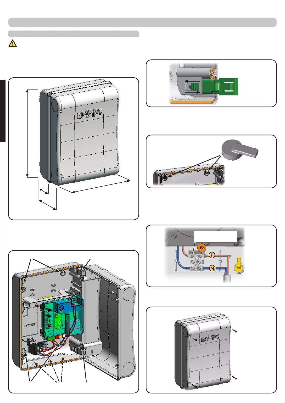
225
Fig.B
Fig.F
Fig.C
Fig.D
Fig.E
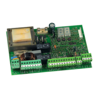
230V -> 2,5A - 250V
115V -> 4A - 120V
Fig.A
130
64
306
BOX LAYOUT
Fig.Bshowsthefour5mmdiam.holesforsecuringthebox
(ref.a)tothewall,thethreefacilitiesforistallingthecablegrip-
persM16/M20/M25(ref.b)andthetwocoverhinges(ref.c).
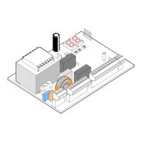
THE BOX CONTAINS THE E024S CONTROL UNIT AND THE
DEVICES TO POWER IT. IT MUST THEREFORE BE HANDLED
WITH CARE DURING ALL INSTALLATION STAGES, TO AVOID
DAMAGING ITS COMPONENTS.
ThedimensionsoftheboxareshowninFig.A:
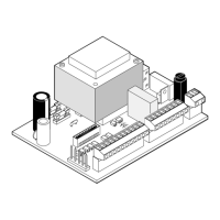
Thecoverhingescanbemovedupwardtoallowopeningthe
boxhousing(Fig.C);theycanalsoberemovedandre-posi-
tionedinordertoenablethecovertoopentotherightorleft.
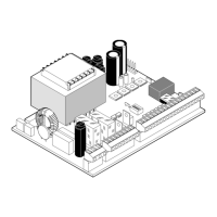
Whenyouhavesecuredtheboxintheselectedposition,cover
thesecuringholes(ref.a Fig.B)andthescrewswiththesupplied
plugsasshowninFig.D.
ConnectthepowercableasshowninFig.E.
Afterhavingconnectedthecontrolboardtothedifferentparts
oftheautomatedsystem,closetheboxbyplacingthecover
onitsseatwithgasket.
Dimensions in mm
ELECTRICAL BOX E024S
Next,tightenthefoursuppliedscrewstoguaranteethedegree
ofprotectionagainstexternalagents(Fig.F).
ENGLISH