CLOSE SAFETY
OPEN SAFETY
CL OP
FSW
TX
TX
RX
RX
STOP
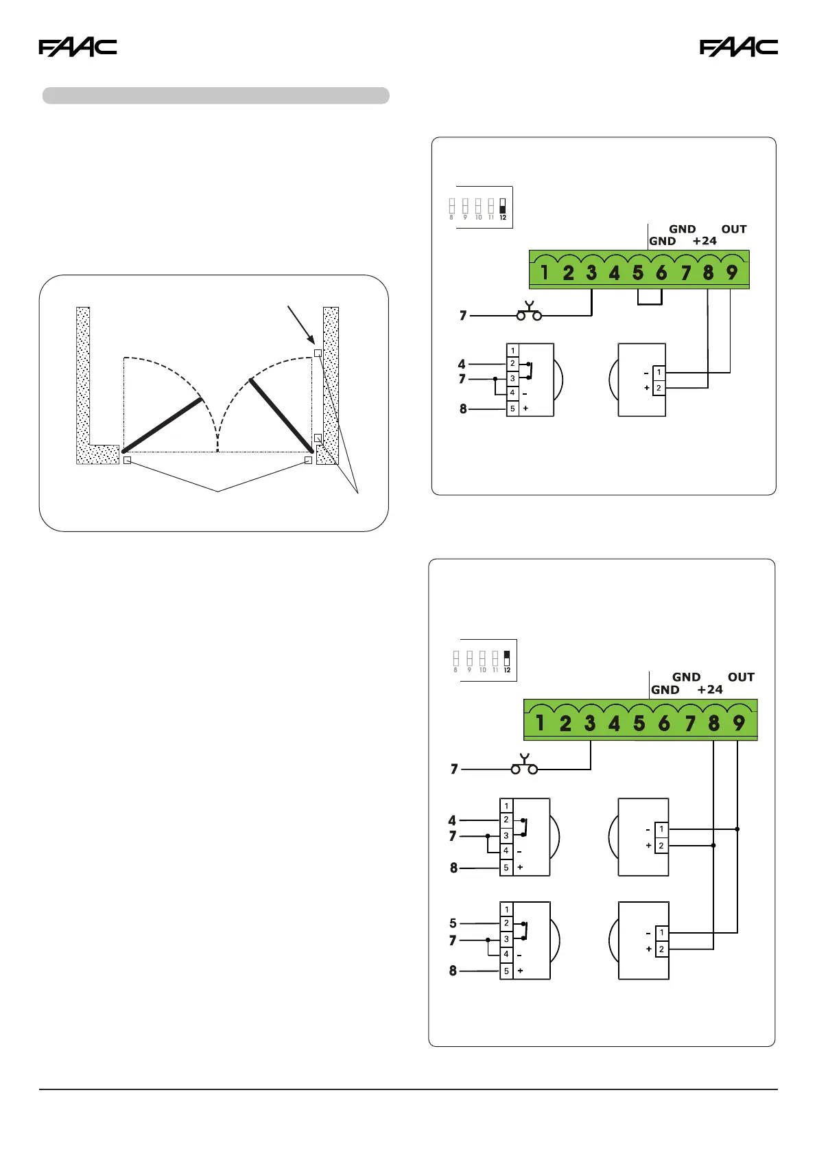
Connection of One Pair of Monitored Opening
Photocells and One Pair of Monitored Closing
Photocells
CLOSE SAFETY
CL OP
FSW
RX TX
STOP
Fig. A6
RX= Receiver Photocell
TX= Transmitter Ptotocell
3. SAFETY DEVICES CONNECTIONS
Fig. A7
Entrapment protection
To comply with the UL325 standard for gate operators every
entrapment zone, as defined in ASTMF2200, must be pro-
tected by two independent entrapment protection devices.
One of the devices is inherent in the E024U control boards
design, the other can be external, like a photocell or an
edge sensor.
See this picture for the photocells positioning:
Fig. A3
Closing Safety Devices
Opening Safety
Devices
Opening Safety Devices:
Are active only during the gate opening movement, and
are suitable for protecting the area between the opening
leaves and fixed obstacles (walls, etc) against the risk of
entrapment
Closing Safety Devices:
Are active only during the gate closing movement, and are
suitable for protecting the closing area against the risk of
entrapment.
Monitored Devices:
Additionaly the UL325 standard requires that every external
entrapment protection device must be monitored for
presence and correct operation. To comply with this
requirement the E024U control board uses the FAILSAFE
function. This function tests the photocells before each
movement of the operator. In case the test fails the
movement is inhibited. This function is enabled by default
on the Closing Safety Input and can be enabled on the
Opening Safety Input using dip-switch 12 of DS1 ON.
The power supply negative of the transmitter must be
connected to the OUT pin (No.9).
See Fig. A6, A7, A8, A10 for wiring examples.
Connection of One Pair of Monitored Closing Photocells
RX= Receiver Photocell
TX= Transmitter Ptotocell
16” or less
DS1
DS1
15