Drives
3.
180
Ref.1912
DDS
HARDWARE
· 124 ·
X1 connector
This connector may be used to connect the modules to each other through
the internal bus communicating the elements of the DDS system with each
other.
All the modules powered with the same power supply must be connected to
this bus and this condition is must to run it.
Together with each module, a connector and a ribbon cable are supplied for
this connection.
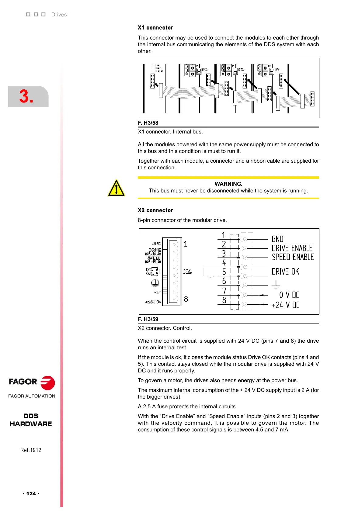
X2 connector
8-pin connector of the modular drive.
When the control circuit is supplied with 24 V DC (pins 7 and 8) the drive
runs an internal test.
If the module is ok, it closes the module status Drive OK contacts (pins 4 and
5). This contact stays closed while the modular drive is supplied with 24 V
DC and it runs properly.
To govern a motor, the drives also needs energy at the power bus.
The maximum internal consumption of the + 24 V DC supply input is 2 A (for
the bigger drives).
A 2.5 A fuse protects the internal circuits.
With the “Drive Enable” and “Speed Enable” inputs (pins 2 and 3) together
with the velocity command, it is possible to govern the motor. The
consumption of these control signals is between 4.5 and 7 mA.
F. H3/58
X1 connector. Internal bus.
WARNING.
This bus must never be disconnected while the system is running.
F. H3/59
X2 connector. Control.
1
8
1
2
3
4
6
5
7
8
DRIVE ENABLE
SPEED ENABLE
0 V DC
+24 V DC
GND
DRIVE OK