1.
F. H1/2
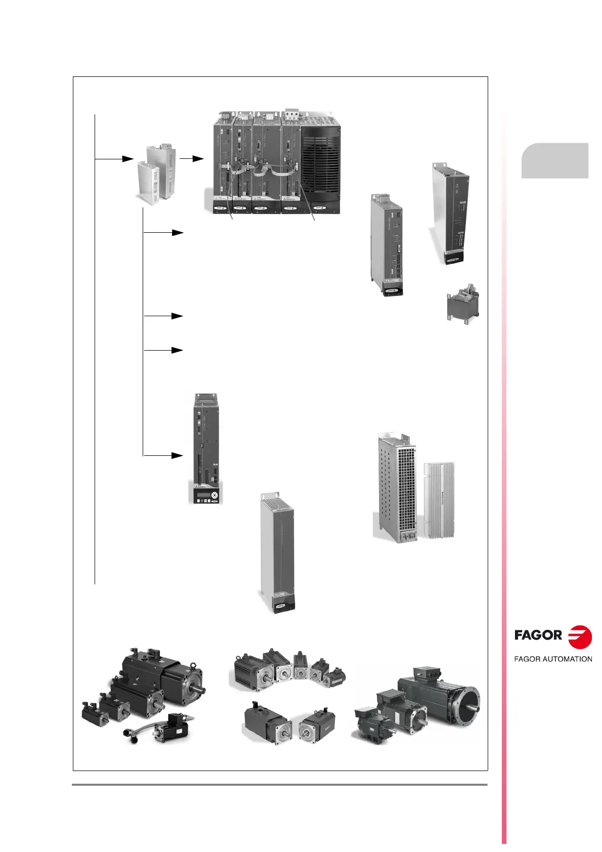
DDS system. Configurations.
for axes: AXD, MMC
for spindle: SPD
Mains filters:
MAIN FILTER
A-A
Non-regenerative
power supplies
Compact drives
·they integrate the power supply·
+ CHOKE XPS-
+ Modular drives:
for axes: ACD, CMC
for spindle: SCD
Capacitor module CM-1.75.
It is connected in parallel to the
power bus (600 V DC).
Resistor modules ER+TH-
/
or
ER+TH-18/
+FAN.
They are connected to the power
supplies, the compact drives or to BPM
module.
PS-65A
+ auxiliary power supply:
APS-24
Regenerative power supplies
·they integrate the auxiliary power supply·
XPS-
Non-regenerative power supplies
· they integrate the auxiliary power supply ·
PS-25B4
for axes: AXD, MMC
for spindle: SPD
+ modular drives:
for axes: AXD, MMC
for spindle: SPD
+ modular drives:
+ CHOKE RPS-
+ Modular drives:
RPS-
Regenerative regulated
power supplies
·they integrate the
auxiliary power supply·
for axes: AXD, MMC
for spindle: SPD
+ BPM
FKM
Synchronous motors
Asynchronous motors
FXM FM7/ FM9
Mains connection.
Three phase 50/60 Hz.TN mains
400 (1-10 %) to 460 (1+10 %) V AC