Drives
3.
Ref.1912
· 135 ·
DDS
HARDWARE
Connectors at slots SL1/SL2
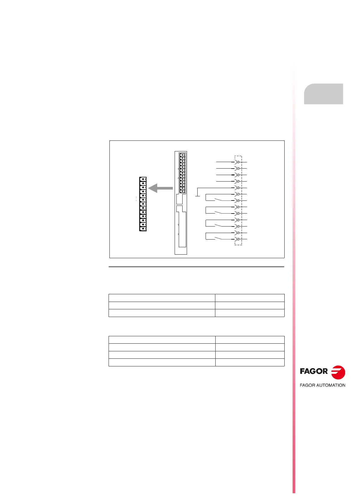
Card A1
The A1 card must always be in slot SL1.
X6-DIGITAL I/Os, digital inputs and outputs
If offers 4 digital inputs and 4 digital outputs, all of them fully programmable.
The digital inputs are optocoupled and referred to a common point (pin 5).
The digital outputs are contact type and also optocoupled.
Each input and output is associated with a parameter. The user may assign
to these parameters, internal Boolean type variables that may be used to
show the system status via electrical contacts. See “man_dds_soft.pdf”
manual.
These assigned Boolean variables are set with the monitor program for PC
(WinDDSSetup).
Digital inputs characteristics
Digital outputs characteristics
F. H3/75
A1 card: X6-DIGITAL I/Os. Digital inputs and outputs.
Maximum rated voltage 24 V DC (36 V DC)
ON/OFF voltage 18 V DC (5 V DC)
Maximum typical consumption 5 mA (7 mA)
Maximum voltage 250 V
Maximum load current (peak) 150 mA (500 mA)
Maximum internal resistance 24
Galvanic isolation voltage 3750 V (1 min)
IN 1
PIN
Phoenix,
3.5 mm
X6 - DIGITA L I/ Os
A1
1
1
X7 - A NA LOG I/ Os X6 - DIG ITA L I/ Os
P2P1
A1 Board
1
13
IN 2
IN 3
IN 4
REF-IN
OUT 1
OUT 2
OUT 3
OUT 4
13
12
11
10
9
8
7
6
5
4
3
2
1