Drives
3.
Ref.1912
· 165 ·
DDS
HARDWARE
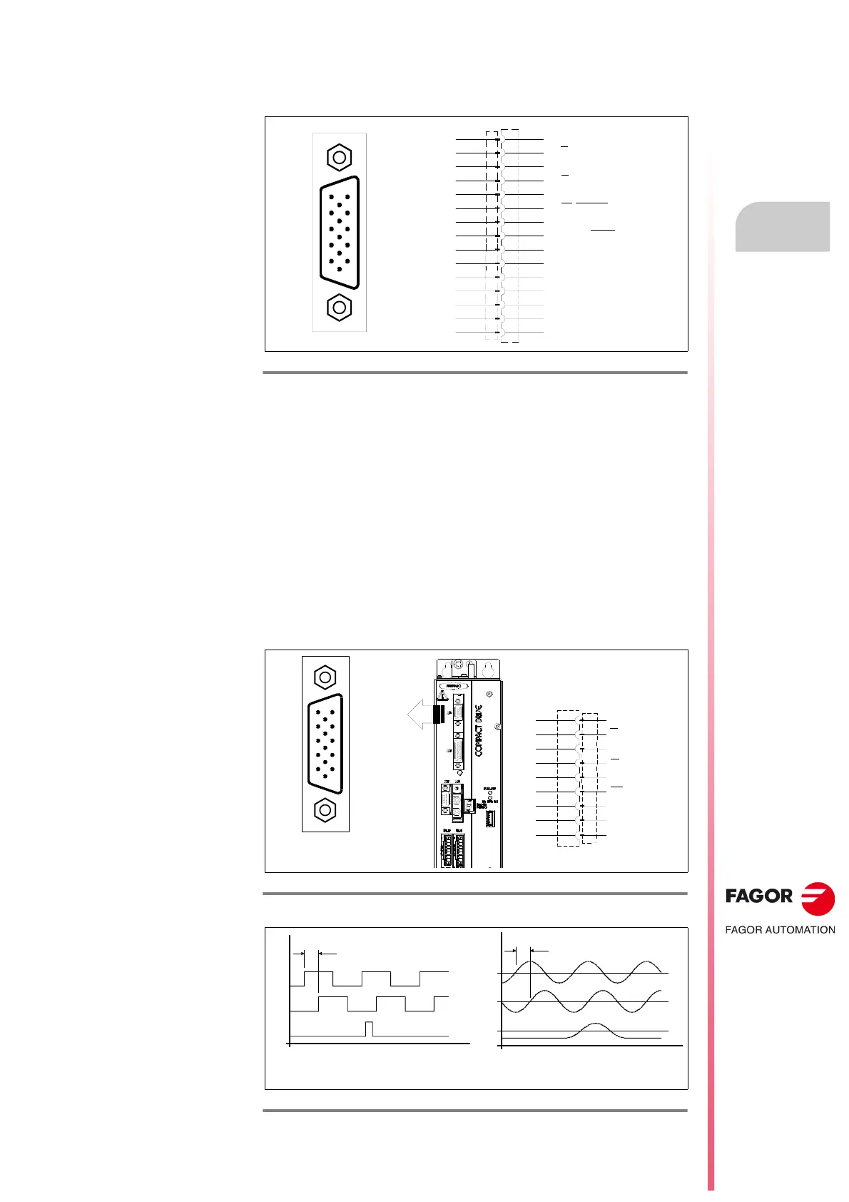
X3. Direct feedback
Having installed a direct feedback card, X3 is a high density (HD) 15-pin sub-
D type female (F) connector.
It supports the following signals:
Square single-ended TTL
Square differential (double-ended) TTL
1 Volt peak-to-peak sinusoidal (1 Vpp)
SSI
EnDat
and the following frequencies:
1 MHz with square signals
500 kHz with sinusoidal signals
The input impedance for sinusoidal signals is 120 .
With external incremental feedback device
F. H3/118
X3 connector. Pinout.
F. H3/119
X3 connector. Signals sent by an external incremental feedback device.
F. H3/120
Characteristics of the square TTL signals and 1Vpp sinusoidal signals.
A
A
I0/DATA
I0
/DATA
+ 485/CLK
GND
2
B
B
- 485/CLK
+ 5 V DC
+ 5 V DC
·SENSOR·
GND
·SENSOR·
CHASSIS
+ 8 V DC
N. C.
1
3
4
5
6
7
8
9
10
11
12
13
14
15
15
14
13
12
11
10
9
8
7
6
1
2
3
4
5
15
14
13
12
11
10
9
8
7
6
1
2
3
4
5
A
A
I0
I0
GND
B
B
CHASSIS
+ 5 V DC
2
1
3
4
5
6
9
11
15
90° PHASE-SHIFT
t
V
A
, V
B
: 0.6 Vpp -1.2 Vpp
V
I0
:
0.5 Vpp
V
A
I
0
V
B
90° PHASE-SHIFT
V
A
I
0
V
B
t
V
OH
> 2.5 V
V
OL
< 0.5 V