Drives
3.
Ref.1912
· 173 ·
DDS
HARDWARE
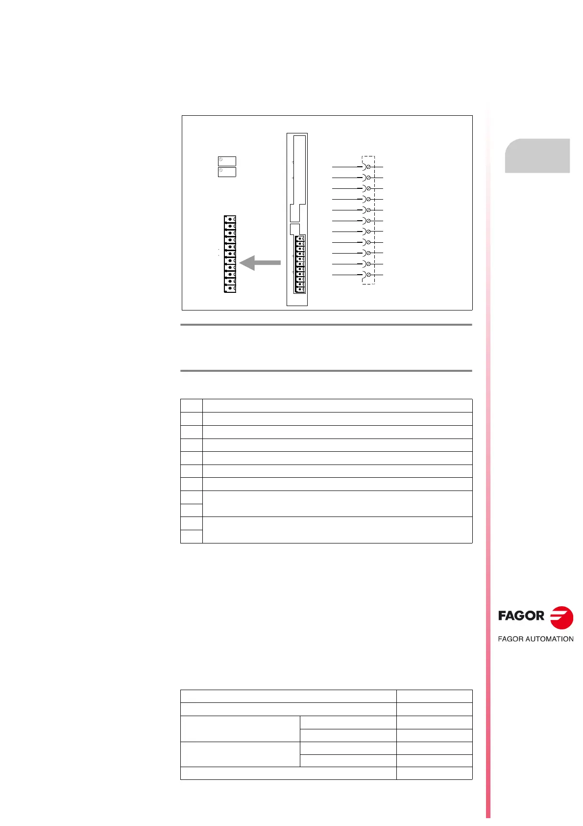
X7-ANALOG I/O, digital inputs and outputs
It offers 2 inputs and 2 outputs , all of them fully programmable.
Each input and output is associated with a parameter.
See “man_dds_soft.pdf” manual.
It offers a ±15 V DC power supply for generating a command easily.
Pinout
Analog input 1
Associated with pins 4 and 5.
It is the usual input for the velocity command (±10 V DC) generated by the
CNC.
Analog input 2
Associated with pins 2 and 3.
It is the auxiliary command input.
Analog input characteristics
F. H3/131
A1 card: X7- ANALOG I/Os. Analog inputs and outputs.
T. H3/30 Pins of connector X7-ANALOG I/O. Description. Analog inputs and
outputs.
1 Chassis
2 Analog input 2 ( - )
3 Analog input 2 ( + )
4 Analog input 1 ( - )
5 Analog input 1 ( + )
6 Adjustment output (-15 V DC) (user)
7 Adjustment output (+15 V DC) (user)
8
Reference for analog output 2 ( - )
Analog output 2 ( + )
9
10
Reference for analog output 1 ( - )
Analog output 1 ( + )
11
Resolution 1.22 mV
Input voltage range ±10 V DC
Input over-voltage Continuous mode 80 V DC
Transients 250 V DC
Input impedance With respect to GND 40 k
Between both inputs 80 k
Voltage in common mode 20 V DC
X7 - A NA LOG I/ Os
A1
1
1
X7 - ANA LOG I/ Os
X6 -DIGITA L I/Os
P2P1
P2
P1
OUT2 -
OUT2 +
OUT1 -
OUT1 +
A1 Board
Phoenix,
3.5 mm
1
11
- 1 5 V DC
+ 1 5 V D C
CHAS S IS
ANALOG INPUT 2 -
ANALOG INPUT 2 +
ANALOG INPUT 1 -
ANALOG INPUT 1 +
PIN
1
2
3
4
5
6
7
8
9
10
11