EasyManuals Logo

Fagor DDS Series User Manual

Fagor DDS Series
406 pages
To Next Page IconTo Next Page
To Previous Page IconTo Previous Page
Page #356 background imageLoading...
Page #356 background image
Connection diagrams
10.
358
Ref.1912
DDS
HARDWARE
· 356 ·
Diagram of the maneuver
F. H10/30
AXD/SCD mixed system, SERCOS/CAN. Diagram of the maneuver.
Important.
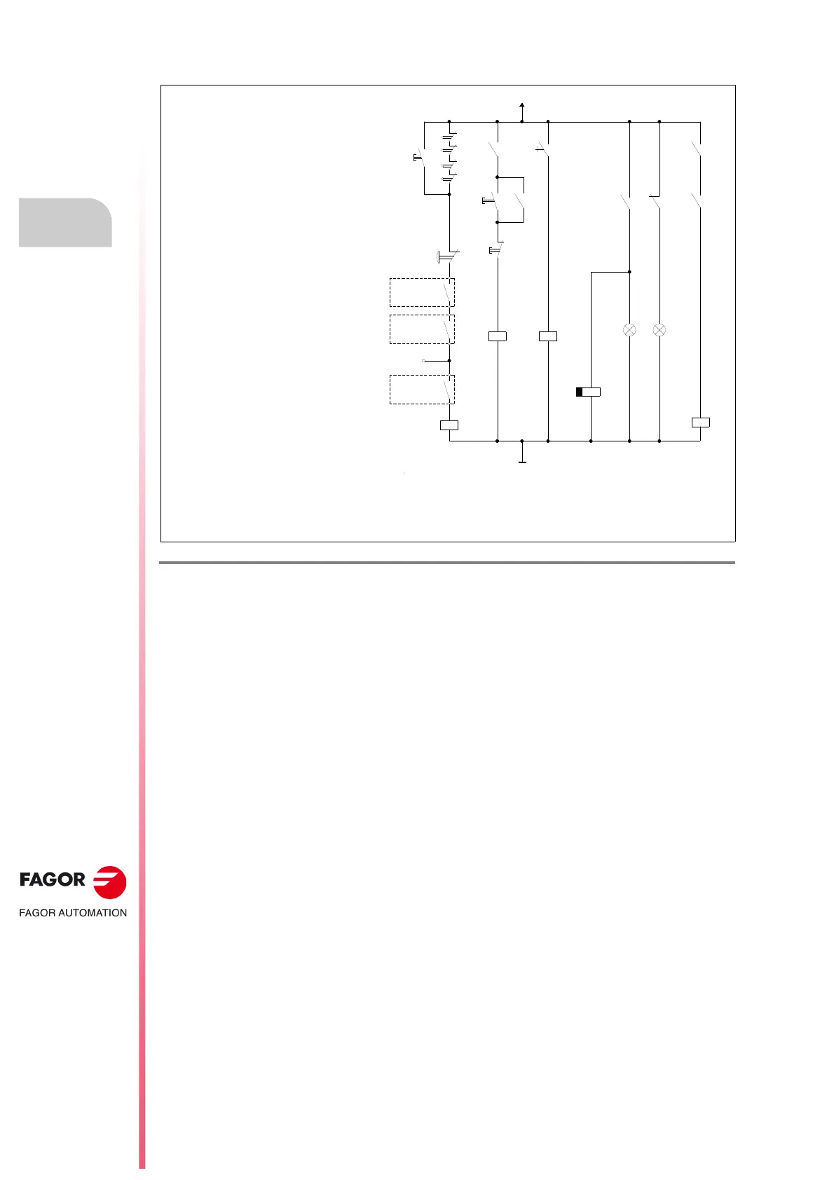
- KA3 is a relay for a delayed deactivation
of contactor - KM1 (t seconds) in order to
be able to keep it closed long enough to
return to mains (with XPS power supply)
the excess energy generated while
braking the motor.
Make sure that the delay “t” programmed
at relay - KA3 is slightly longer than the
braking time of the application.
The delay disconnection time “t” to be
programmed at relay - KA3 must be
greater than
the total amount of time
required to brake the motor to a full stop.
See parameter GP9
in the “man_dds _soft.pdf” manual.
Note.
CNC EMERG. will always be assigned to I1/O1 of the PLC with an 8055/55i CNC. With an 8070 CNC, it may
be assigned to any I/O of the PLC. The contacts associated with relays - KA2 and - KA3 are shown in fig.
F. H10/28
and fig.
F. H10/29.
+24VDC
X+
X-
Z+
Z-
KA1
KA3
ON
KM1
KA2
KA1
BRAKE LINE
BRK
(See GP9)
ON OFF
GND
EMERGENCY LINE
-KA2
-KM1
ON
Green
OFF
Red
DELAY
OFF
-KA3
DRIVE
ENABLES
(See GP9)
SPEED
ENABLES
SYSTEM
SPEED
ENABLE
OFF
EMERG.
STOP
XPS
SYSTEM OK
S_SCD
DR.S OK
I1 PLC
-KA1
CNC EMERG.
O1 PLC
t seconds
KA2 KA2

Table of Contents

Questions and Answers:

Question and Answer IconNeed help?

Do you have a question about the Fagor DDS Series and is the answer not in the manual?

Fagor DDS Series Specifications

General IconGeneral
BrandFagor
ModelDDS Series
CategoryDC Drives
LanguageEnglish

Related product manuals