Power supplies
2.
Ref.1912
· 43 ·
DDS
HARDWARE
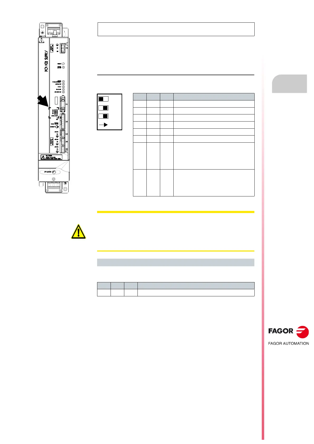
The non-regenerative power supply PS-25B4 has three switches on the
front and next to connector X1 (see figure) for selecting the external Ballast
resistor. If you have a model like this one, refer to the attached table to select
the right resistor model according to the setting of the switches that enables
the ·I
2
t· protection.
For the switch combination shown in the figure and verified in the table, the
ballast resistor selected would correspond to the ER+TH-18/1800.
NOTE. This is the current model with three micro-switches to configure
the selection of the Ballast resistor installed.
T. H2/7 Layout of the Ballast resistor selector switches.
represents, in the figure, the moving element of the switch.
S3 S2 S1 RESISTOR
OFF OFF OFF
Internal
OFF OFF ON
ER+TH-18/1100
OFF ON OFF
ER+TH-18/1000+FAN
OFF ON ON
ER+TH-18/1800
ON OFF OFF
ER+TH-18/2200
ON ON OFF
RM-15 (discontinued)
ON OFF ON
ER+TH-18/1500+FAN or
ER+TH-18/2000+FAN
Note.
If you wish to install a NON-
FAGOR resistor, please read below.
ON ON ON
ER+TH-18/1500+FAN or
ER+TH-18/2000+FAN
Note.
If you wish to install a NON-
FAGOR resistor, please read below.
Model currently in the catalog
PS-25B4
WARNING. When installing a NON-FAGOR resistor, only use this switch
setting when the power of your resistor is greater than any of the ones
shown in this cell of the tables provided by FAGOR. Ignoring this warning
MAY CAUSE THE DESTRUCTION of the resistor WITHOUT PRIOR
WARNING. Therefore, make sure to install your own protection system
when installing a NON-FAGOR resistor of lower power.
Example
S3 S2 S1 RESISTOR
OFF ON ON
ER+TH-18/1800