Power supplies
2.
Ref.1912
· 49 ·
DDS
HARDWARE
The internal circuits of the non-regenerative power supplies PS-65A require
an external 24 V DC supply. This is why its connector X2 has three more pins
than for the PS-25B4 power supply that integrates an auxiliary power supply.
The internal circuits are protected with a 1.25 A fuse.
The following table shows the values for gap, tightening torque, sections and
other data of the plug-in connector for X2.
The next table shows the signals and other considerations related to each
pin of connector X2:
X3|X4|X5|X6 connectors
These connectors belong to the auxiliary power supply integrated into the
main power supply PS-25B4.
Connector X3 receives power from mains. It admits a voltage between 400
V AC and 460 V AC.
This auxiliary power supply generates 24 V DC and its purpose is to feed
the control circuits of the module itself. Also, it supplies up to 10 A of this
DC voltage through connectors X4|X5|X6. These three connectors are
identical and offer greater connecting flexibility.
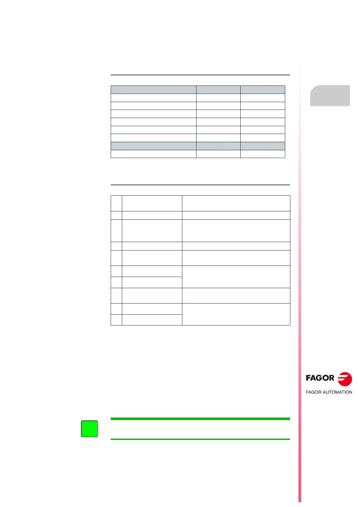
T. H2/10 Connector X2. Characteristics of the pins.
Connector data PS-25B4 PS-65A
Nr of poles 7 10
Gap (mm) 5.08 5.08
Min/max tightening torque (N·m) 0.5/0.6 0.5/0.6
Screw thread M3 M3
Min./max. section (mm²) 0.2/2.5 0.2/2.5
Rated current In (A) 12 12
Wire data
Length to strip (mm) 7 7
T. H2/11 Connector X2. Description of the pins.
1
Error RESET
System error RESET input
(24 V DC ; 4.5-7 mA).
2
N. C. Not Connected
3
GND
0 volts reference for digital inputs.
Error RESET (1) and
System Speed Enable (5).
4
N. C. Not Connected
5
System Speed Enable
General system speed enable.
(24 V DC ; 4.5-7 mA).
6
System OK
Contact indicating module status.
It opens in case of failure.
Limit 1 A at 24 V.
7
System OK
8
Chassis
Chassis connection
(only on PS-65A power supplies)
9
0 V DC
Voltage supply of the control circuits (only on
PS-65A power supplies) between 21 V DC
and 28 V DC. Max. consumption 1 A.
10
+24 V DC
INFORMATION. There is no need to install external protection fuses in
these power lines. They are already integrated into the power supplies.