58
Traffic-Control
EN
You will find further explanations on certain functions, for instance the
flip-flop or the interval timer switch, in chapter 8 »Interesting facts« of
the present instruction manual.
TIP
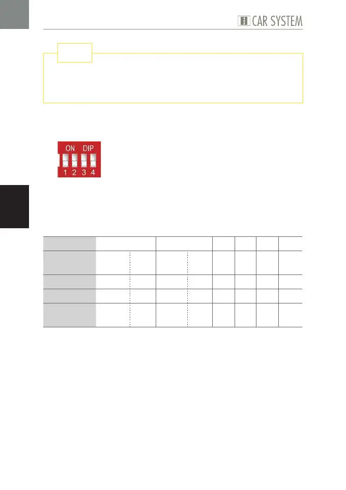
Program 1
Fig. 6: DIP configuration Program 1
This program contains two complete bus stops as well as four further pos-
sible ways of switching the outputs for a predefined period of time, depen-
ding on an input signal. Programs 1 to 4 merely differ as to the diverse
activation periods used.
Possible use Bus stop 1 Bus stop 2 X 1 X 2 X 3 X 4
Sensor at
input
E1 E2 E3 E4 E5 E6 E7 E8
activates ST AB ST AB K K K K
at output A1 A2 A3 A4 A5 A6 A7 A8
for the
period of
Poti 1 1 s Poti 2 1 s 1 s 5 s 10 s 15 s
Table 6: Program 1
X
Set the DIP as required, see Fig. 6.
X
Connect the components, see Table 6.
X
If necessary, set the desired period using the potentiometers.
ADVICE: Please also take into consideration the schematic drawings repro-
duced in the appendix to the present instruction manual.