62
Traffic-Control
EN
Program 5
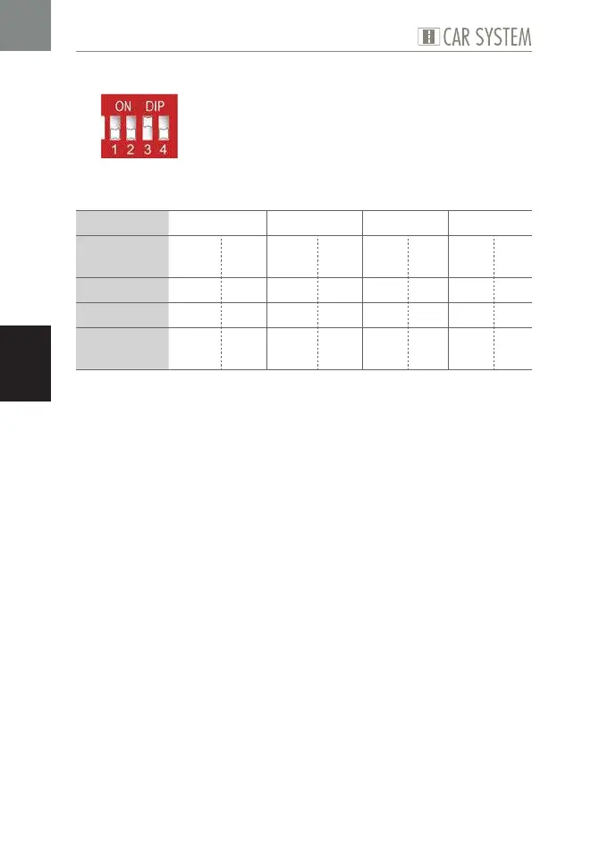
Fig. 10: DIP configuration Program 5
This program allows to control four bus stops.
Possible use Bus stop 1 Bus stop 2 Bus stop 3 Bus stop 4
Sensor at
input
E1 E2 E3 E4 E5 E6 E7 E8
activates ST AB ST AB ST AB ST AB
at output A1 A2 A3 A4 A5 A6 A7 A8
for the
period of
Poti 1 1 s Poti 2 1 s 15 s 1 s 20 s 1 s
Table 10: Program 5
X
Set the DIP as required, see Fig. 10.
X
Connect the components, see Table 10.
X
If necessary, set the desired period using the potentiometers.