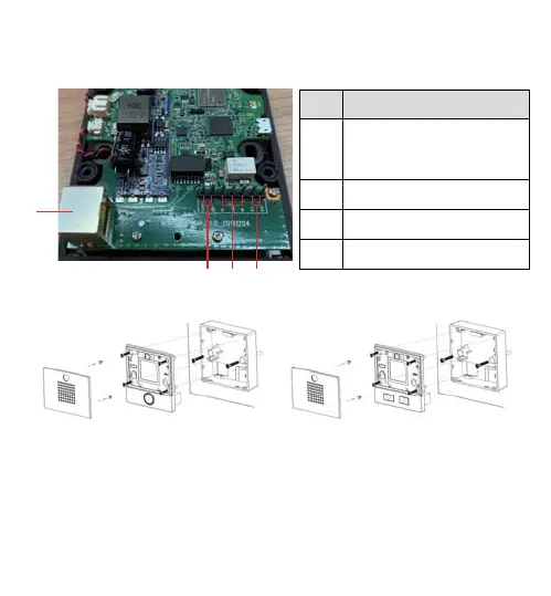
2) Interface description
Open the rear case of the device, there is a row of terminal blocks for connecting
the power supply, indoor switch. The connection is as follows:
ʒ
ʓʕʔ
Serial
number
Description
Ethernet interface: standard
RJ45 interface, 10/100M
adaptive, it is recommended
to use five or five types of
network cable
Power interface: 12V/1A input
A set of short-circuit output
interfaces
A set of short-circuit input
interfaces
1
2
3
4
3) Installation Diagram
Cover Main body Back Shell Cover Main body Back Shell
1) Wall Mount: Attach the installation dimension drawing to the position to be installed,
use the electric drill to punch the hole in the 2 screw holes marked, and use the
hammer to drive the screw into the drilled hole.
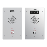
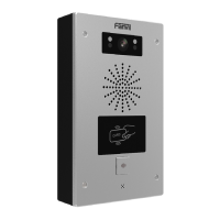
Figure 3-1 Three Major Parts of i10&i10V Figure 3-2 Three Major Parts of i10D
Built-in: Attach the installation dimension drawing to the position to be installed, open a
groove of the same size according to the size, use the electric drill to punch the hole in
the 2 screw holes marked, and use the hammer to drive the screw into the drilled hole.

 Loading...