77X INSTALLATION & OPERATION MANUAL
771/772/773/774 MODELS
60
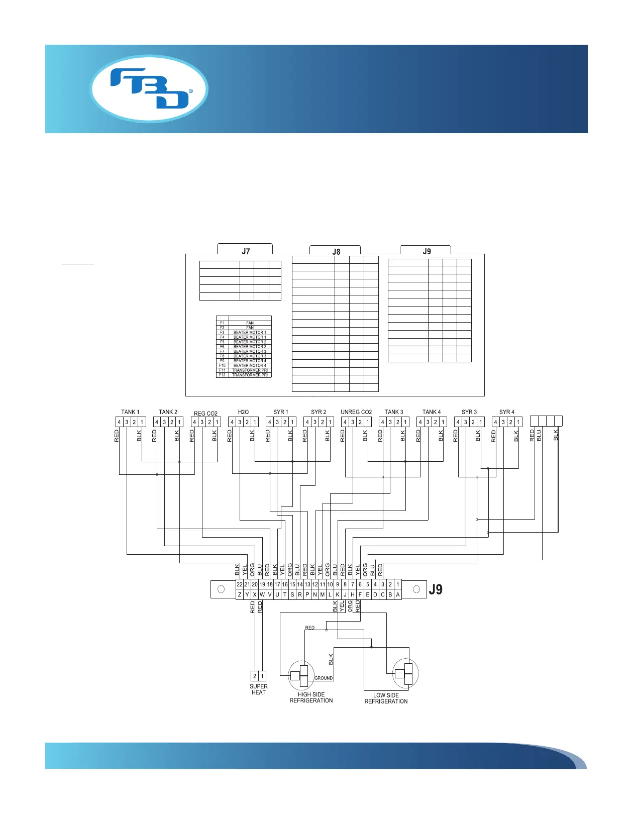
11.5 Electrical Wiring Diagrams (Standard Dispensers)
Figures 11.10 through 11.12 show the electrical wiring diagrams for the standard 774 dispenser and are representative
of the standard 772 and 773 dispensers with the exception of the number of barrels.
FUSE PARTS
Harness Functions 772 773 774
BEATER MOTOR 1
■ ■ ■
BEATER MOTOR 2
■ ■ ■
BEATER MOTOR 3
■ ■
BEATER MOTOR 4
■
Harness Functions 772 773 774
SOL1
■ ■ ■
SOL2
■ ■ ■
SOL3
■ ■
SOL4
■
CO2 1
■ ■ ■
CO2 2
■ ■ ■
CO2 3
■ ■
CO2 4
■
REF 1
■ ■ ■
REF 2
■ ■ ■
REF 3
■ ■
REF 4
■
DEF 1
■ ■ ■
DEF 2
■ ■ ■
DEF 3
■ ■
DEF4
■
Harness Functions 772 773 774
TANK 1
■ ■ ■
TANK 2
■ ■ ■
TANK 3
■ ■
TANK 4
■
SYR 1
■ ■ ■
SYR 2
■ ■ ■
SYR 3
■ ■
SYR 4
■
REG CO2
■ ■ ■
H2O
■ ■ ■
UNREG CO2
■ ■ ■
ACTIVE CHARGE
■ ■ ■
GROUND
3.3 VDC
ANA - GND
ANA - GND
3.3 VDC
3.3 VDC
ANA - GND
ANA - GND
3.3 VDC
OUTPUT
5VDC
OUTPUT
VOLTAGE 5VDC
ACTIVE CHARGE
4 123
VOLTAGE
NOTE: DIAGRAM
SHOWN FOR 774
Figure 11.10 Electrical Diagram for Standard 772, 773, and 774 Dispensers
1 OF 3