INSTALLATION FLT
®
Series FlexSwitch
TM
10 Fluid Components International LLC
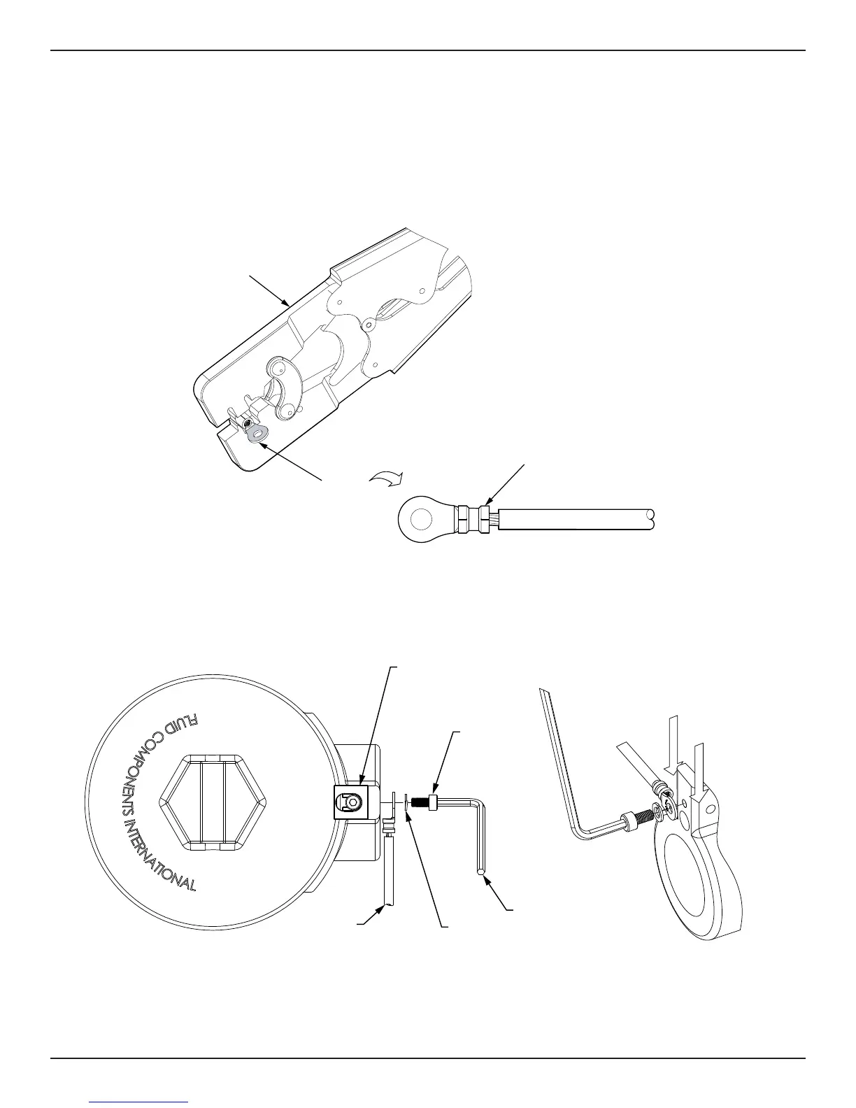
3. Place center of ring lug barrel in appropriate crimping tool chamber. Squeeze tool handles together with just enough force to hold barrel
in place (do not deform barrel).
4. Insert stripped end of ground wire into barrel. Place the wire such that the insulation does not enter barrel and that the stripped wire end
does not extend beyond barrel.
5. While holding the wire in place, squeeze the tool handles together until the ratchet releases, then allow the tool handle to open fully.
See Figure 2-6.
Caution:
The crimping jaws bottom before ratchet releases. This feature ensures maximum electrical tensile performance of the crimp.
Do NOT re-adjust the ratchet.
Figure 2-6 Crimping Ground Wire Ring Lug
Figure 2-7 Installing Ring Lug Terminated Ground Wire
6. Install ground wire ring lug with end of lug barrel touching the side of the enclosure’s mounting boss as shown in Figure 2-7. Place the
ring lug on either side of the mounting boss as needed for the installation. Install with the hardware in this order: socket cap screw, split
lock washer, ring lug. Torque cap screw to 23 in-lb (2.6 N-m).
CRIMPING TOOL
RING LUG
RING LUG WITH
CRIMPED GROUND WIRE
C01333-1-1
(a) Enclosure Top View (b) Detail View
Position ring lug barrel
on either side of
enclosure’s
mounting boss.
ENCLOSURE
GROUND SCREW
MOUNTING BOSS
M4 SOCKET
CAP SCREW
SPLIT
LOCK WASHER
RING LUG
TERMINATED
GROUND WIRE
M4 HEX KEY
C01334-1-1