CHAPTER 3
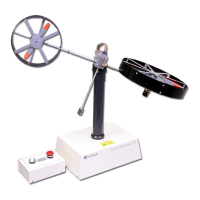
TWIN ROTOR MIMO SYSTEM
Installation and Commissioning PCL – 812 Card Settings
33-007-0 3-1
3. Switch And Jumper Settings for the PCL-812 Card
The PCL-812 contains components which can be damaged by static
electricity. Before removing the PCL-812 board from its conductive
packaging, touch your hand on a grounded metal object such as the case of
your PC. Avoid touching the components on the board or the plated edge
connectors.
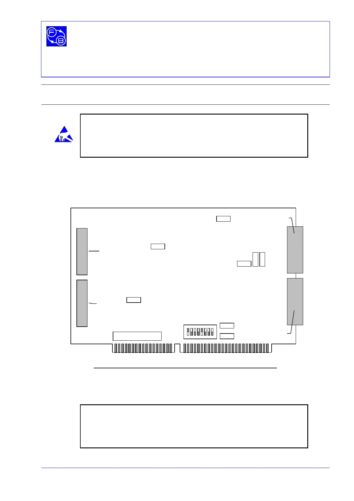
Before installing the PCL-812PG interface card into your computer make sure that the
switches and jumpers shown in Fig. 3.1 are set correctly, as detailed in this section.
Figure 3.1: PCL-812PG Interface Card - Switch and Jumper positions
Note: The board shown above is a 16 bit short board. Some users may have
the 8 bit full length PCL- 812 board for which the SW1 switch settings are
different. If you have this board refer to the settings in the following section
for the 8 bit board.
Other settings and cable connections are the same for both boards.
JP5
JP2
JP1
JP9
JP8
JP7
JP6
JP4
JP3
Digital Out
Digital In
Analogue I/O CN1
Analogue I/O CN2
12 534
678
SW1
ON
☞