CHAPTER 2
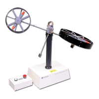
TWIN ROTOR MIMO SYSTEM
Installation and Commissioning Mechanical Assembly
33-007-0 2-1
2. Mechanical Assembly
The MIMO Unit is dis-assembled for transit. Follow the instructions below for re-assembly
and refer to Fig. 2.1.
•
Remove the cover from the base unit by removing 8 x M4 screws.
•
Remove 4 x M4 counter-sunk screws from the bottom of the tower.
•
Attach the tower to the base cover using 4 x M4 counter-sunk screws with the
tower on top of the base, ensuring that the vertical axis locking screw is on the right
hand side viewed from the front of the base unit.
•
The horizontal shaft, to which the rotor assembly attaches, has a flat, on which the
horizontal axis locking screw locates when screwed down. Rotate the horizontal
shaft until the locking screw locates on to the flat and screw the locking screw tight.
Attach the rotor arm to the top of the tower so that the arm is
horizontal
and
secure to the shaft using the Allen key provided.
•
Locate the counter-weight pendulum into the hole in the rotor arm boss and secure
using the Allen key provided. The pendulum should be on the front of the unit when
viewed from the front of the base unit.
•
Connect cables - there are two ribbon cable connections inside the base unit, and
one ribbon cable connection at the top of the rotor boss.
•
Replace the base cover, with the tower attached to the base unit, and secure using
the 8 x M4 screws previously removed.
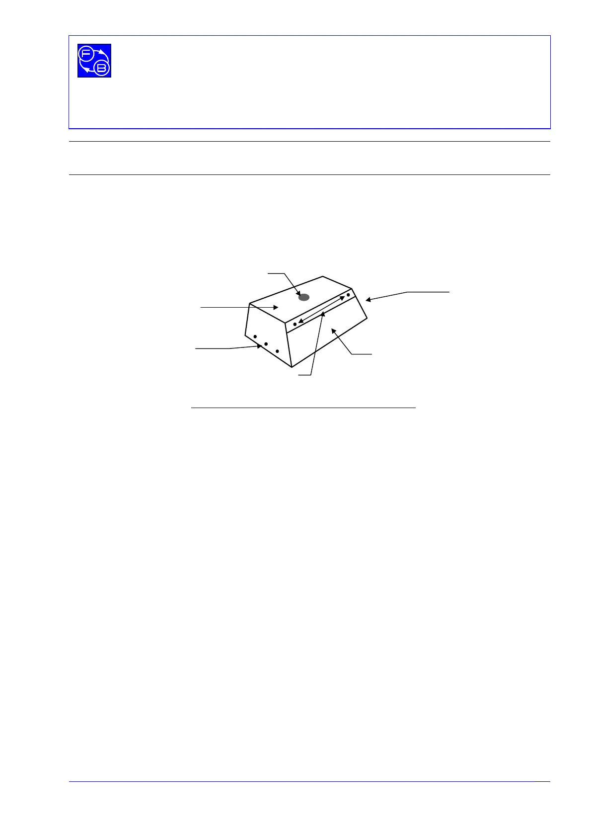
Rear of Base Unit
Base Unit cover
3 x M4 screws
either end
3 x M4 screws
either end
2 x M4 screws
Fig 2.1: Showing position of base unit cover screws
Mounting for
Tower