CHAPTER 3
TWIN ROTOR MIMO SYSTEM
Installation and Commissioning PCL – 812 Card Settings
33-007-0 3-3
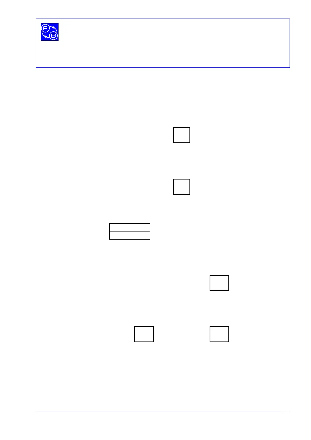
3.2 JUMPER SETTINGS
The Jumpers on the PCL-812 board should be set in the positions indicated below.
JP1 - Trigger Source Selection
JP1
INT O
TRG O
EXT O
JP2 - Counter Input Clock Selection
JP2
INT O
CLK O
EXT O
JP3, JP4 - D/A Reference Selection
JP3 O O O D/A1
JP4 O O O D/A2
INT VREF EXT
JP5 - IRQ Level Selection
234567X
OOOOOOO
OOOOOOO
JP5
JP6, JP7 - DMA Channel Selection
13X 13X
OOO OOO
OOO OOO
JP6 JP7