CHAPTER 4
TWIN ROTOR MIMO SYSTEM
Installation and Commissioning PCL-812 Card Installation
33-007-0 4-1
4. Installation of the PCL-812 Card And Cables
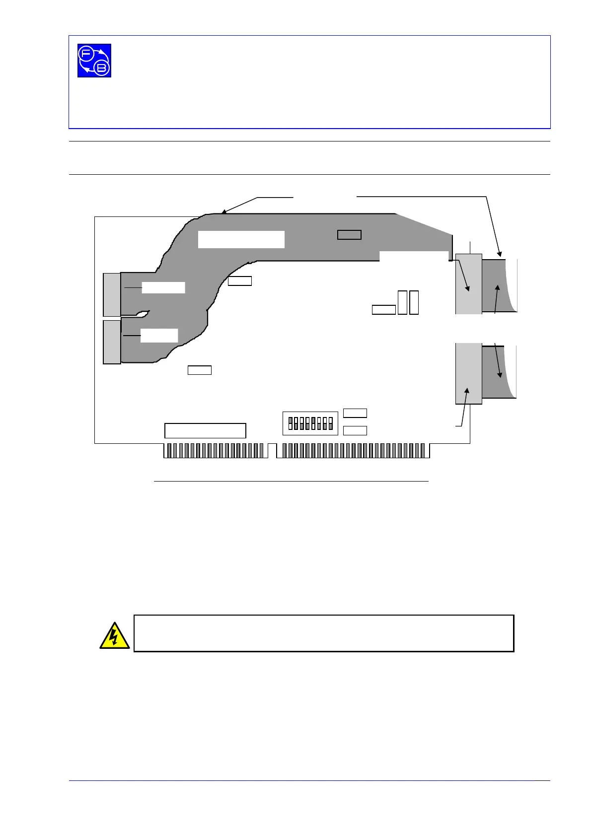
Figure 4.1: PCL- 812 Interface Card Ribbon Cable connections
Two
slots are required at the rear of the PC - one for the two 20 way analogue port
sockets, and one for the 40 way socket at the end of the wide ribbon cable for the digital
ports. Use screws to secure the card and ribbon socket plates to the casing of the PC.
Carefully install the interface card in a spare slot on the PC motherboard (or in a slot on
the passive backplane if your PC has this type of architecture - common with some 19
inch rack mounted PC’s). If in any doubt as to the correct procedure consult the
documentation supplied with the PC.
Turn OFF and disconnect the mains power supply
BEFORE opening the computer
Before opening the computer it is important to ensure that the computer is switched off
and that the mains power supply is not connected.
Once you have opened the computer, check to see if there are any other cards installed,
for example a network or sound card. It is important to determine the addresses of any
such cards as your Twin Rotor MIMO System will not function correctly
if there is another
card using all, or part of, the address space assigned to the PCL-812PG interface card.
12 534
678
JP5
JP2
JP1
JP9
JP8
JP7
JP6
JP4
JP3
Di
ital Out
Digital In
Analogue I/O CN1
Analogue I/O CN2
SW1
Wide ribbon cable
2 narrow
ribbon cables
Red band on
cable
on top
ON