FERNO/MAN/01/18/159/UK 9 Pegasus Trolley
User Guide 2-Part Track-Mounted Floor Lock (255-mm Gauge Unwin System)
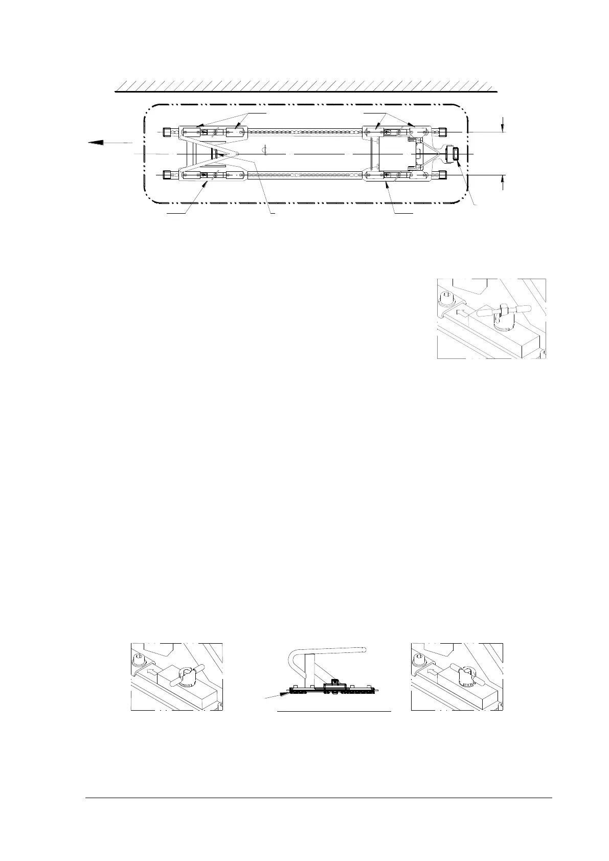
1. Removal of Head End and Foot End Lock Assemblies
On each Unwin locking device, rotate the plunger
crossbar and turret anticlockwise a quarter of a turn.
Lift the plunger crossbar from its U-slot in the turret,
and rotate it slightly to rest it on top of the turret.
Remove the assembly from the tracking by sliding the
assembly along the track half a hole pitch (12-13 mm)
and lifting clear.
2. Installation of Head End Lock Assembly
On each Unwin locking device, rotate the plunger crossbar until it snaps into
the U-slot on the turret (diagram A below). Do not rotate the turret clockwise
at this stage.
Close to the positional guide plate fitted to the vehicle floor between the
tracking at the head end, engage the pegs on the underside of the lock
assembly in the tracking (diagram B).
Slide the assembly towards its required position until both plungers locate in
the track.
For each of the two Unwin devices, use the plunger crossbar to rotate the
turret clockwise a quarter of a turn (diagram C). The assembly will be locked
rigidly to the tracking.
Test for security and safety.
3 Installation of Foot End Lock Assembly
Install foot end lock assembly in exactly the same way as above adjacent to the
positional guide plate at the foot end.