10
© Ferno s.r.l. MU-086-G Rel.01102019
XT Extrication Device
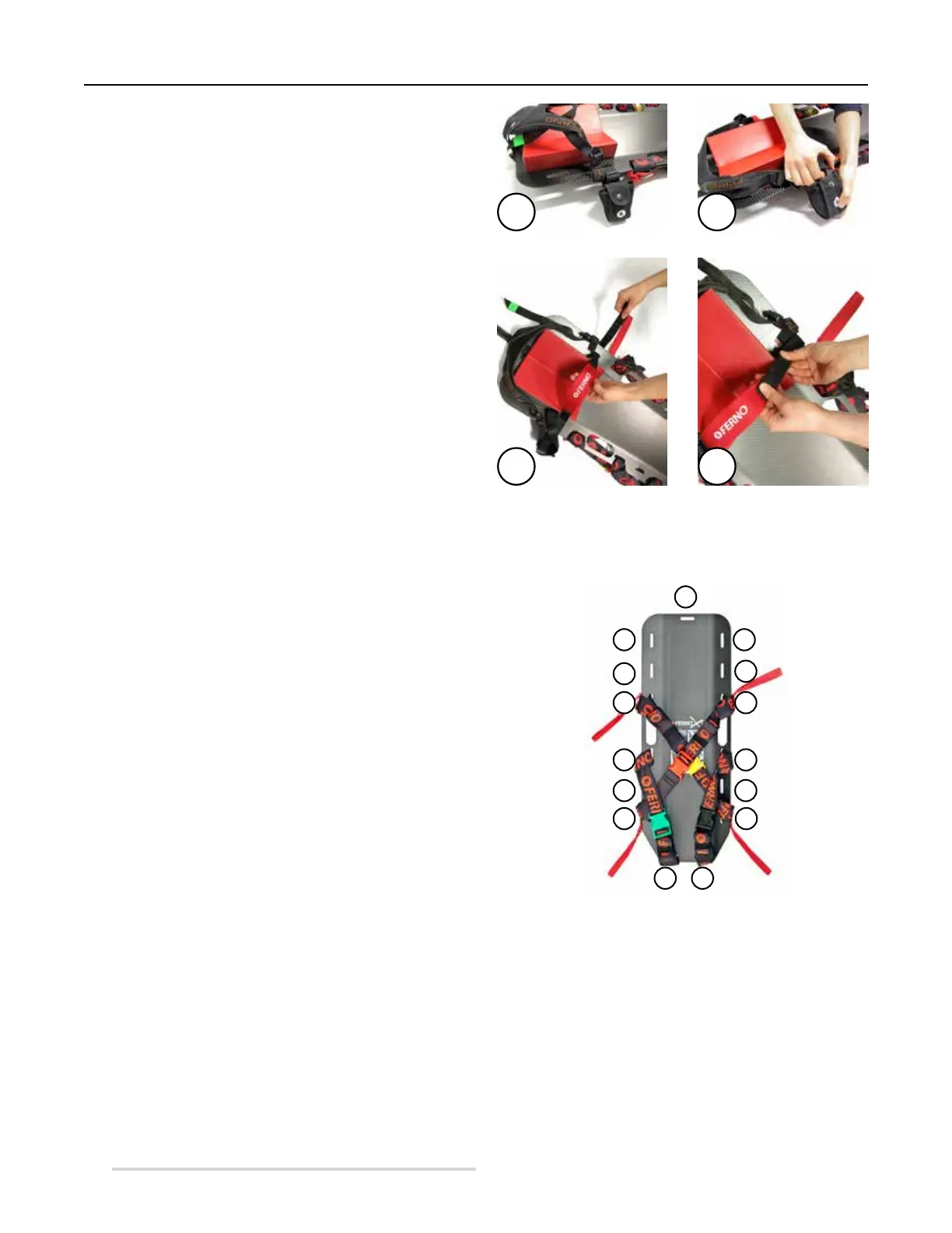
4.3 Chin strap QHI application
The neoprene chin strap, stored in a special bag, can be
secured on the extrication device using side hole no. 14 (to
identify the hole see Figure 4, page 10).
1. Extract the neck strap from the bag attached to the
extrication device (Figure 3B).
2. Insert the opposite end of the strap in hole no. 3 on the
right (to identify the hole see Figure 4, page 10).
3. Overlap and secure the two Velcro straps to ensure a
perfect closure (Figure 3D).
When the strap is not used, store it in the suitable bag.
Figure 3 - Neoprene red strap application
3A 3B
3C 3D
Conguration of the extrication device
4.4 Restraint conguration
The XT extrication device is equipped with two upper chest
restraints (yellow and red) and two lower groin restraints
(black and green).
The upper chest restraints must be applied in a crossed
conguration,whilethegroinrestraintsmustbesecuredon
the same side. Each restraint is composed of two parts, one
with a male end and the other with a female end. The male
end must be fastened to the female end. Always make sure
that the two ends are well secured.
The upper chest restraints are provided with red handles for
lifting and carrying.
The restraints must be applied before using the XT device.
For their application and the identication of the right
hole on the device, refer to Figure 4. In Figure 4 holes are
numbered clockwise from 1 to 15.
Figure 4 - Restraint conguration (operator view)
HEAD END
FOOT END
RIGHT
SIDE
LEFT
SIDE
1
15
14
13
12
11
10
9 8
7
6
5
4
3
2