16
© Ferno s.r.l. MU-086-G Rel.01102019
XT Extrication Device
Use of the extrication device
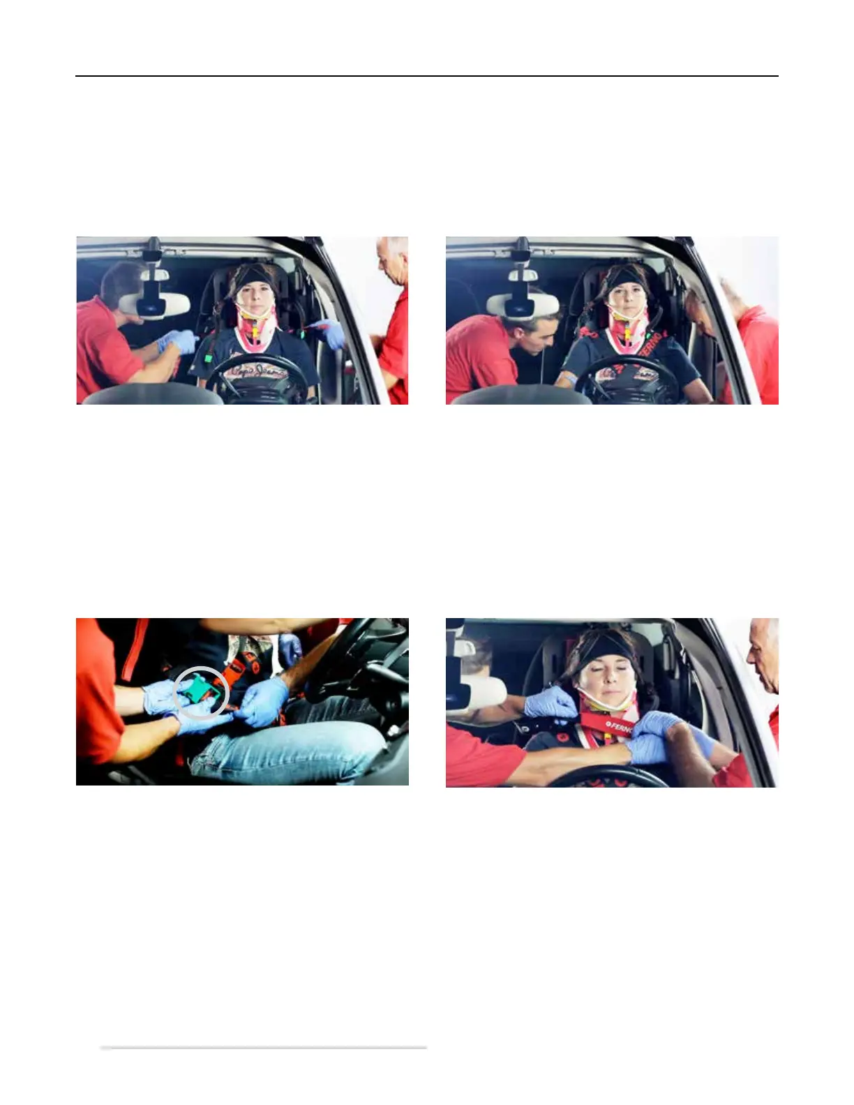
6. Operator 2: while operator 1 keeps holding the cervical spine of the patient, operator 2 applies the triangular head
immobiliser, arranging it with care immediately above the patient's eyebrows (Figure 15). The correct positioning of the
head immobiliser reduces the risk of it moving upwards or downwards.
7. Both operators:positionthechestrestraints(yellowandred)incrossedconguration(Figure16)andfastentheupper
section to the lower one with the buckles provided. If necessary, they suitably adjust the restraints' tension. In this phase,
the operators must ensure that the red lifting and carrying handles remain free above the patient's shoulders, in order to
ndandseizethemeasilyduringthenalextricationphase.
Figure 18 - Cervical spine nal fastening
Figure 15 - Triangular head immobiliser applied Figure 16 - Application of chest restraints
(yellow and red)
8. Both operators: position the groin restraints (black and green), arranging them under the patient's legs, each one on its
side of the board. They fasten the lower section of the restraint to the upper one using the buckles provided (Figure 17),
and suitably adjust their tension to secure the patient to the extrication device. Suitably adjust the restraints to avoid any
compression/constriction for the patient.
9. Operator 1: once all restraints have been applied and fastened, operator 1 takes the chin strap from its bag, adjusts its
length and gives the opposite end to operator 2 (Figure 18).
Figure 17 - Green restraint buckled