12 ferrismowers.com
specific sequences. To learn what combination and sequence
of controls to use for various tasks see the Operation section.
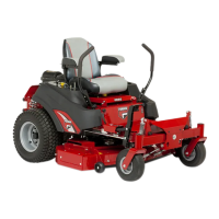
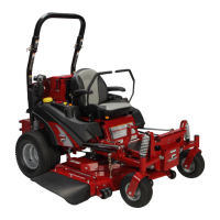
Zero-Turn Rider Controls
4
Callout Control Name
A Deck Lift Pedal
B Cutting Height Adjustment Pin
C Deck Lift Lock Lever
D Ground Speed Control Levers
E Seat Adjustment Levers
F Transmission Oil Fill / Tanks
G Transmission Release Levers
H Fuel Tank Cap
I Fuel Level Gauge
J Removable Floor Plate
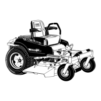
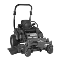
Deck Lift Pedal, Cutting Height Adjustment Pin, and Deck
Lift Lock Lever: These controls are used to adjust the cutting
height of the mower deck.
Depress the deck lift pedal (A, Figure 5) until the deck lift lock
lever (B) locks the mower deck into the 4-1/2" (11,43 cm)
TRANSPORT position. Place the cutting height adjustment
pin (C) into the hole for the desired cutting height. Depress
the deck lift pedal, move the deck lift lock lever outwards,
and slowly release the deck lift pedal until it rests against the
cutting height adjustment pin.
5
Cutting Height Adjustment Pin
Deck Lift Lock Lever
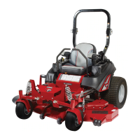
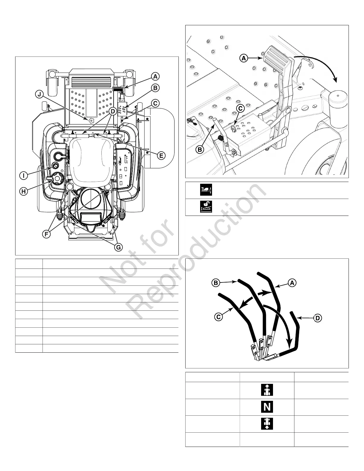
Ground Speed Control Levers: These levers control the
ground speed and direction of the rider. The left lever controls
the left rear drive wheel and the right lever controls the right
rear drive wheel.
6
Callout Icon Description
A FORWARD
B NEUTRAL
C REVERSE
D N/A NEUTRAL LOCK
POSITION
 Loading...