32 ferrismowers.com
exposed when the left hand spindle cover was removed).
Carefully release the tension on the idler arm.
5. Remove the old belt from the remaining pulleys and
replace with a new belt.
6. Install the new belt.
• 44" Mower Deck:Make sure that the V-side of the
belt runs in the pulley grooves of the PTO clutch
pulley (E, Figure44) and the right hand spindle pulley
(B - exposed when the right hand spindle cover was
removed). Make sure that the back side of the belt
contacts the face of the rear stationary idler pulley (F)
and the adjustable idler pulley (G).
• 48" Mower Deck:Make sure that the V-side of the
belt runs in the pulley grooves of the PTO clutch
pulley (E, Figure45), the right hand spindle pulley
(B – exposed when the right hand spindle cover
was removed), and the center spindle pulley (F).
Make sure that the back side of the belt contacts the
faces of the front stationary idler pulley (G), the rear
stationary idler pulley (H) and the adjustable idler
pulley (I).
7. Rotate the idler arm (D,Figures44and45)counter-
clockwiseand install the belt on the left hand spindle
pulley.
8. Set the mower deck to the 3” (7,6 cm) cutting position.
9. Determine for the correct spring length for your machine:
• For units with44"Mower Decks:5-3/4" (14,6 cm) .
• For units with48"Mower Decks:6" (15,2 cm).
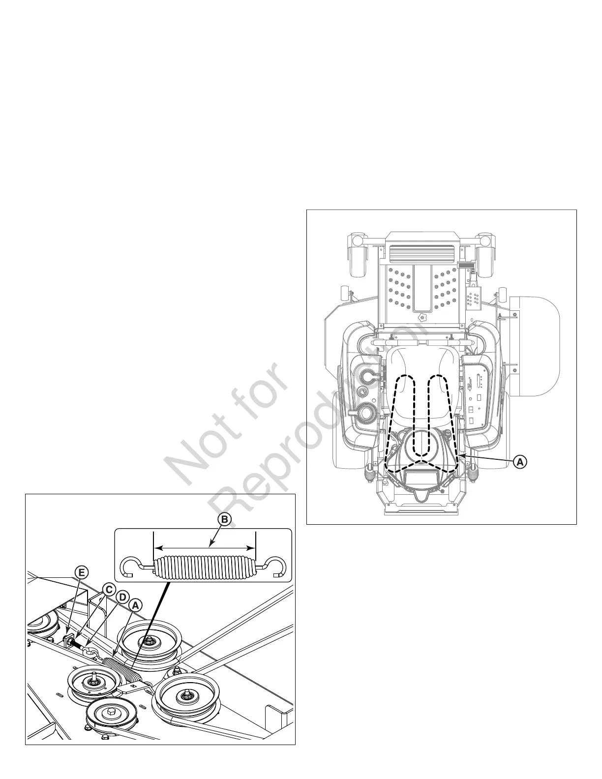
10. Measure the coil-to-coil length of the belt tensioning
spring (A, Figure46). The coil-to-coil measurement (B)
should equal the measurement as indicated in step #9.If
the measurement is not correct, the spring will need to be
adjusted. If the measurement is correct, skip to step #14.
46
11. Loosen the jam nut (C) on the spring anchor eye bolt (D).
12. Turn the adjustment nut (E) until the measurement is
achieved.
13. Tighten the jam nut.
14. Re-install the spindle covers and the floor pan.
15. Run the mower deck under no-load condition for about
five (5) minutes to break in the new belt.
Transmission Drive Belt Replacement
This zero-turn rider is equipped with a transmission drive belt
(A, Figure 47) that is located under the engine deck of the
rider.
47
Inspect the Condition of the Transmission Drive
Belt
Service Interval: Every 400 hours or annually.
1. Park the machine on a flat, level surface such as a
concrete floor. Engage the parking brake, disengage the
PTO, turn the ignition switch to OFF, and remove the
ignition key. Wait for all moving parts to stop.
2. Visually inspect the belt (A, Figure 47) for cracks, frayed
edges, burn marks, or any other damage. If the belt is
damaged it must be replaced.
3. To replace the transmission drive belt the PTO clutch
must be removed from the engine's crankshaft so it is
recommended that replacing the transmission drive belt
be a dealer only service procedure.
Cleaning the Battery and Cables
This unit is equipped with a maintenance-free BCIU1 battery.
 Loading...