29
3. To re-install the floor pan: Reverse the removal
procedure.
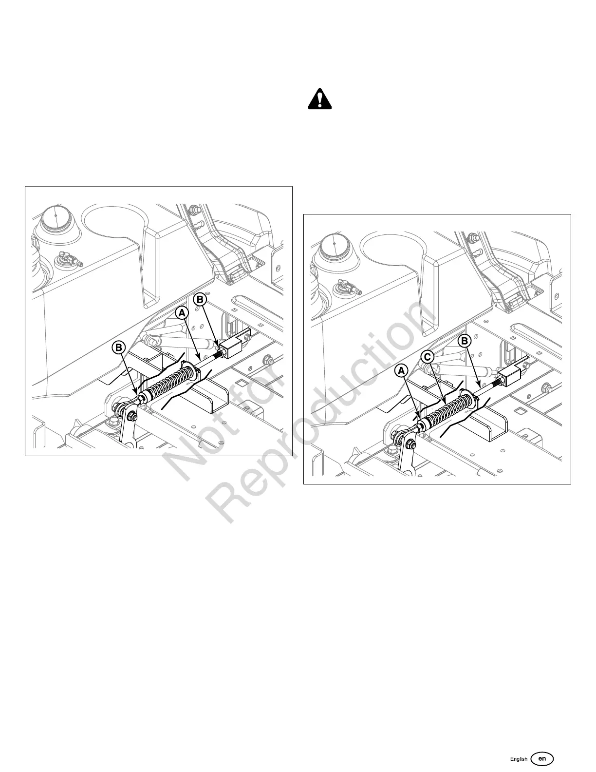
Neutral Adjustment
Each ground speed control lever on this machine is
connected to a transmission by two linkage rods and a
pivoting arm. The lower rod that connects the transmission
to the pivoting arm is set at the factory and should not be
changed for neutral adjustment purposes. The neutral
adjustment is achieved by changing the length of the upper
linkage rod (A, Figure 39) that connects the ground speed
control lever to the pivoting arm.
39
Determining if adjustment is necessary:
Lock the ground speed control levers in the NEUTRAL
position. If either of the zero-turn rider’s tires turns; then the
upper linkage rod associated with that side of the machine will
need to be adjusted.
Note:Perform this adjustment on a hard, level surface such
as a concrete floor.
1. Disengage the PTO, engage the parking brake, and turn
off the engine.
2. There are two nuts (B) on the upper linkage rod. Loosen
the nuts and turn the upper linkage rod to adjust.
• If the machine creeps forward, turn the upper linkage
rod clockwise (while standing at the rear of the
machine, facing forward);
• If the machine creeps backward, turn the upper
linkage rod counter-clockwise (while standing at the
rear of the machine, facing forward).
3. Lock the jam nuts when neutral is achieved.
Note:This adjustment should not be performed while the
machine is running. It may take several attempts to achieve
neutral, depending on how much the machine creeps.
Return-to Neutral Adjustment
Prior to performing this procedure the Neutral Adjustment
procedure must be completed.
WARNING
To avoid serious injury, perform adjustments only with
engine stopped, key removed, and rider parked on level
ground.
1. Position the ground speed control levers into the
NEUTRAL position.
2. Loosen the set collar (A, Figure 40) on the upper linkage
rod (B).
40
3. Position the set collar along the upper linkage rod until it
contacts and very lightly compresses the neutral return
spring (C).
4. Move the ground speed control levers into the operating
position, pull rearward, and release.
5. Move the ground speed control levers out towards the
NEUTRAL position.
• if the ground speed control lever aligns with the notch
in the neutral lock plate, adjustment is complete;
• if the ground speed control lever stops it's return
motion past the notch (while standing at the rear of
the machine), re-position the set collar so the neutral
return spring is less compressed.
• if the ground speed control lever stops it's return
motion before the notch (while standing at the rear
of the machine), re-position the set collar so that the
neutral return spring is more compressed.
6. Repeat the process as necessary until the ground speed
control lever aligns with the notch in the neutral lock plate.

 Loading...