43
11. Reinstall the PTO belt. See Mower Drive Belt
Replacement for instructions.
Rear Suspension Adjustment
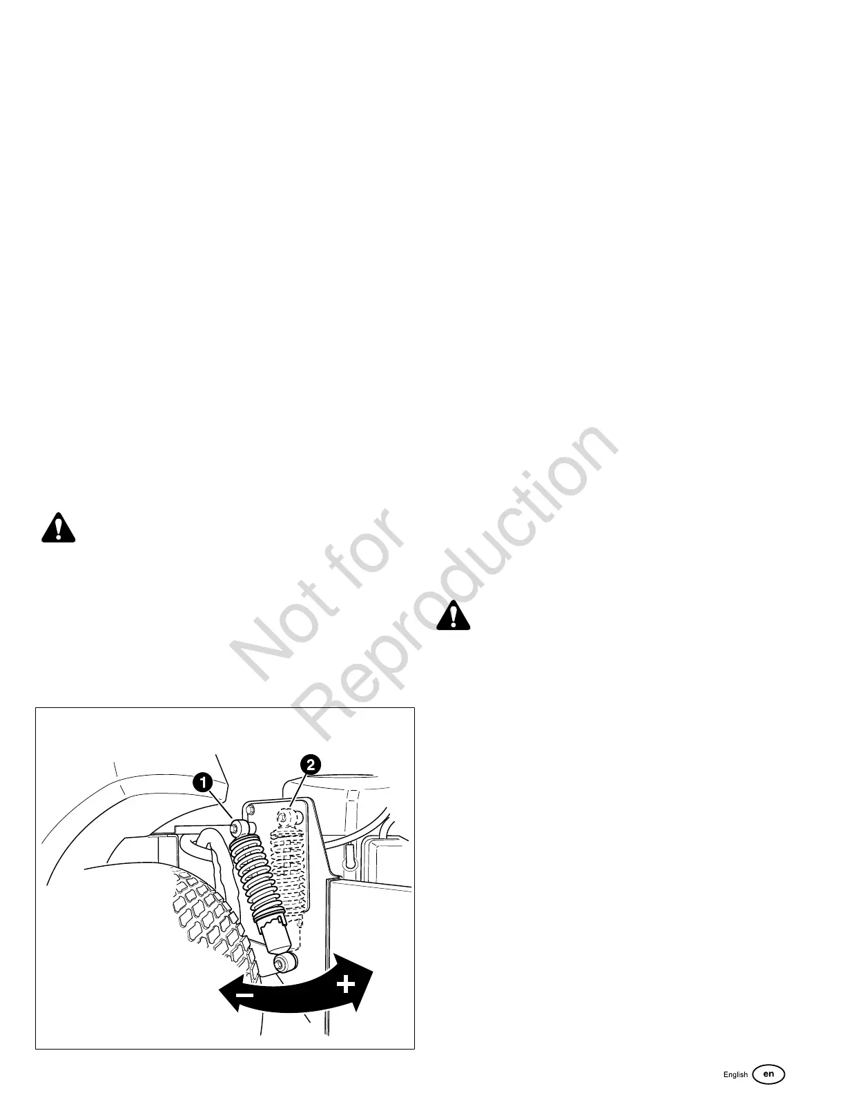
The shock assembly can be adjusted in two ways to allow the
operator to customize the ride according to operator’s weight
and/or operating conditions. You have the option of adjusting
the spring pre-load and/or the upper mounting position.
Items to consider before adjusting the suspension.
• Less spring pre-load should be used with light weight
operators, which will provide a softer, more cushioned
ride.
• More spring pre-load or upper mounting position #2
should be used with heavy weight operators, or when a
rear-mount grass bagger system is installed, which will
provide a stiffer, more rigid ride.
To Adjust the Spring Pre-Load:
1. Park machine on a flat, level surface. Disengage the
PTO, stop the engine and engage the parking brake.
2. Raise the rear of the machine and secure with jack
stands. Chock the front wheels to prevent the machine
from rolling.
3. Remove the rear drive tires.
WARNING
Use two hands when adjusting the shock springs. This will
prevent the wrench from slipping while pressure is applied.
4. See Figure58.Using the supplied spanner wrench (p/n
5022853), insert the tip of the wrench into the notch in the
pre-load adjuster. While holding the wrench in place with
one hand, turncounter-clockwiseto increase the pre-
load, turnclockwiseto decrease the pre-load. Make sure
both shocks are set to the same amount of pre-load.
58
5. Reinstall the rear drive tires. Torque the lug bolts to 85-95
ft/lbs. (115-129 Nm). Remove the jackstands from under
the machine.
NOTE: Spanner wrench is located under the seat on the
right-hand side of the machine.
To Adjust the Upper Mounting Position:
1. Park machine on a flat, level surface. Disengage the
PTO, stop the engine and engage the parking brake.
2. Raise the rear of the machine and secure with jack
stands. The jack stands must under the bumper. Chock
the front wheels to prevent the machine from rolling.
3. Position the jack under the cross member that ties the
suspension arms together and slowly raise the rear
suspension to relieve the pressure on the upper shock
mounting bolts.
Note:This will require small adjustments to the jack’s
position. The shock should move freely on the mounting bolt
when the pressure is relieved.
4. Remove the upper shock mounting hardware and pivot
the shock to the position #2 (see Figure58). Adjust the
jack to align the shock mounts to the shocks.
5. Reinstall the upper shock mounting hardware and tighten
securely.
6. Remove the jack from under the suspension cross
member.
7. Remove the jack stands from under the machine.
Battery Maintenance
DANGER
Be careful when handling the battery.
Battery acid can cause severe burns. Avoid contact with
skin. Wear protective gear (safety goggles/face shield and
gloves) when working with the battery.
Keep the battery out of reach of children.
To avoid an explosion, keep open flames and sparks away
from the battery, especially while charging.
When removing or installing battery cables, disconnect the
negative cable FIRST and reconnect it LAST. If not done in
this order, the positive terminal can be shorted to the frame
by a tool.
Cleaning the Battery and Cables
This unit is equipped with a maintenance-free BCIU1 battery.
1. Disconnect the cables from the battery, negative [-] cable
first (A, Figure 59).

 Loading...