96 EN
cod. 3540000272 - Rev. 01 - 01/2024
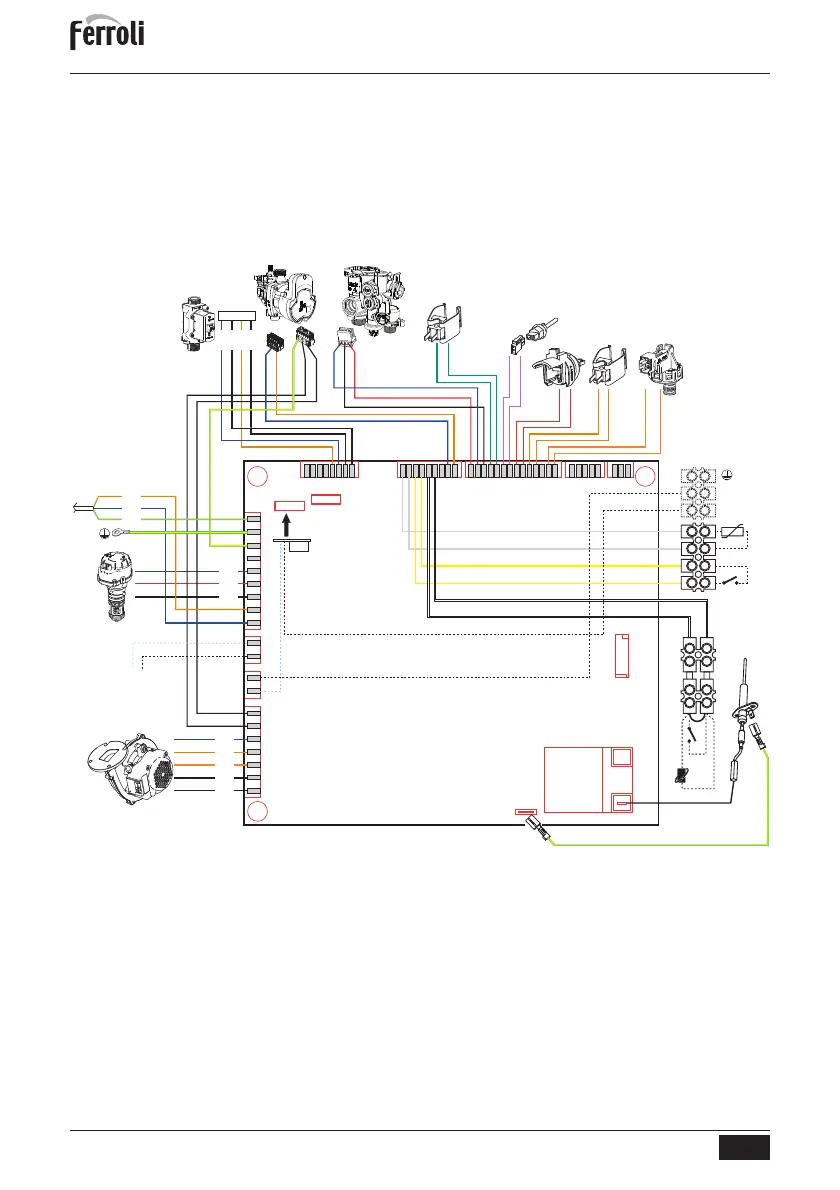
4.6 Wiring diagram
16 Fan
32 Heating circulating pump
34 Heating temperature sensor
42 DHW temperature probe
44 Gas valve
72 Room thermostat (not supplied)
81 Ionization/ignition electrode
95 Diverter valve
114 Water pressure switch
136 Flowmeter
138 External probe (optional)
139 Remote timer control (optional)
186 Return sensor
191 Fume temperature sensor
288 Frost protection kit
A ON/OFF switch (configurable)
fig. 46- Wiring diagram
A
Attention: Remove the jumper on the terminal block before connecting the room thermo-
stat or the remote timer control.
To connect multiple zones of the plumbing system controlled by thermostats with voltage-
free contact and there is a need to use the timer control as a function of remote boiler con-
trols, it is necessary to connect the voltage-free contacts of the zones to terminals 1-2 and
the timer control to terminals 5-6.
ALL CONNECTIONS TO THE TERMINAL BLOCK MUST BE WITH VOLTAGE-FREE
CONTACTS (NOT 230V).
X04X03
X02
X01
X16
X05
X07 X08 X09
18 19 114
17 19
15
X11
X01-1
X01-2
X08-11
X08-10
X08-14
X08-12
X08-13
X07-1
X07-2
X08-1
X08-2
X08-7
X08-6
X08-5
X08-4
X08-9
X08-8
LC32
114
34
42
16
44
191
136
95
186
X01-3
X01-4
X01-5
X01-6
X01-7
X04-7
X04-6
X04-5
X05-4
X05-3
X05-2
X05-1
32
81
X04-8
X04-9
X04-1
230V
50Hz
1234
56
GROUND
A
138
288
N
L
X04-3
72
139
 Loading...