3 Product overview
The motor controller CMMP-AS-...-M0 has a digital I/O-interfac e [X40] for control of
the STO safety func tion.
2
3
1
0V
24 V
C2
C1
0V-B
STO-B
0V-A
STO-A
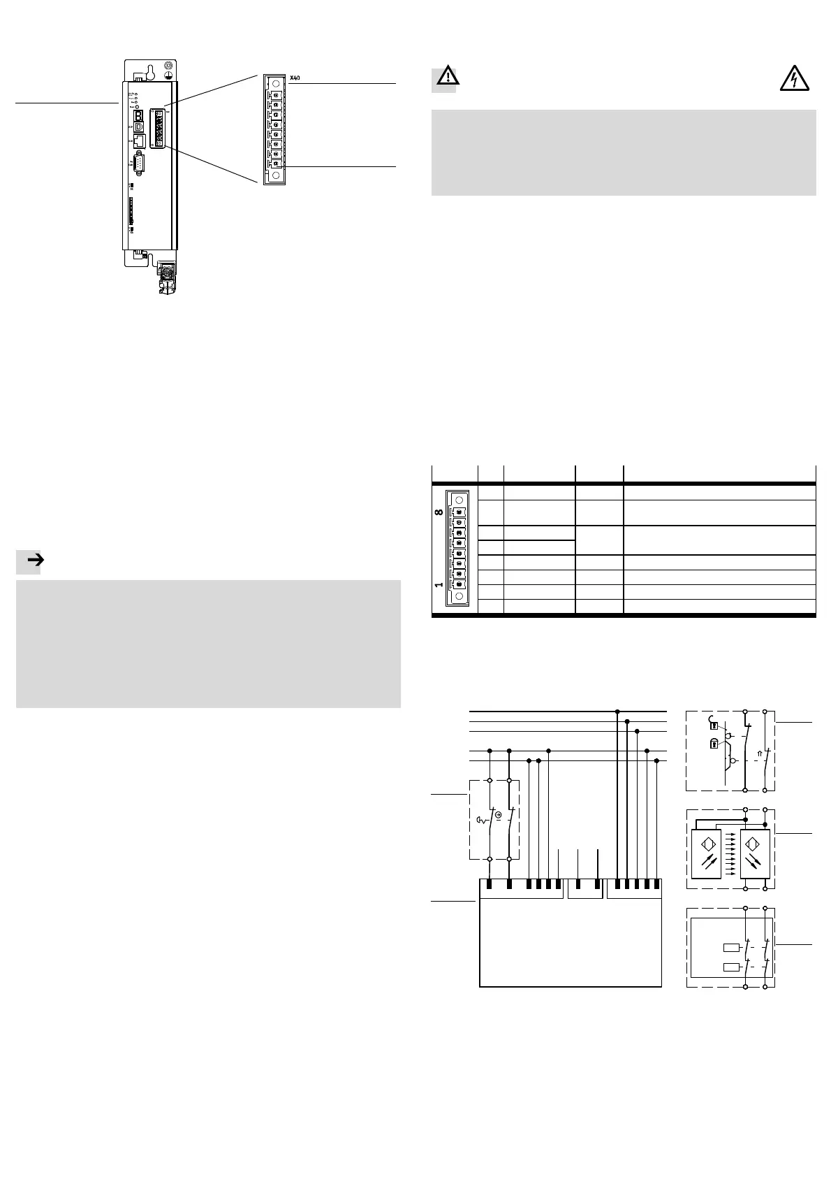
1 Motor controller CMMP-AS -…-M0
2 Digital I/O interface [X40] for con-
trol of the STO function
3 Pin 1 of the interface [X40]
Fig. 1 Motor controller CMMP-AS -...-M0
4 Function and application
The motor controller CMMP-AS-...-M0 has the following safety-related perform-
ance characteristic.
– “Safe Torque Off” (STO) function,
– Potential-free acknowledgment contact,
4.1 Description of the s afety function
The power supply to the drive is reliably disconnected via the active safety function
STO “Safe Torque Off”. The drive cannot generate torque or force and so cannot
perform any hazardous movements. There is no monitoring of the standstill posi-
tion.
The machine must be stopped in a safety-oriented manner, e.g.via a safety switch-
ing device.
Note
There is a risk that the drive will advance if there are multiple errors in the
CMMP-AS-…-M0.
Failure of the motor controller output phase during STO status (simultaneous
short circuit of 2 power semiconductors in different phases) may result in a lim-
ited detent movement of the rotor. The rotation angle / path corresponds to a
pole pitch. Examples:
– Rotary axis, synchronous machine, 8-pin movement < 45° at the motor
shaft.
– Linear motor, pole pitch 20 mm movement < 20 mm at the moving part.
4.2 Control ports STO-A, 0V_A / STO-B, 0V_B [X40]
The safety function STO is requested solely through switching off of the control
voltage (0 V) at the two digital c ontrol ports STO-A and STO-B. Safety-oriented
circuitry for additional interfaces at the CMM P-AS...-M0 is not required or inten-
ded.
Cross-circuit detection in the input circuit is not carried out.
According to the specification of the safety function, both levels must be identical
at S TO-A/B. If both channels are not actuated simultaneously, the STO is still act-
ive at the first request.
The finite state machine in th e motor controller internally monitors the driver sup-
ply voltage after the control ports have been ac tivated. The level change for both
ports must occur within the discrepancy time (established: 100 ms). If a c hannel is
not switched off, this is interpreted as an error and results in an error message.
Always switc h STO-A a nd STO-B simultaneously.
Test impulses of safety controls are tolerated within a certain range section 12,
technical data – electrical data.
4.3 Feedback c ontact C1, C2 [X40]
The status of the motor controller is reported back to an external safety switching
device through a potential-free acknowledgment contact (normally open).
The feedback contact has a single channel and may only be used for monitoring.
5 Mounting / dismantling
The safety switch is integrated into the motor controller CMMP-AS-…-M0 and can-
not be dismantled.
6 Electrical installation
6.1 Safety instru ctions
The requirements of EN 60204-1 must be fulfilled during installation.
Warning
Danger of electric shock from voltage sources without protective
measures.
• Use only PELV (protective extra-low voltage) circuits in accordance with
EN 60204-1.
Also take into account the general requirements for PELV circuits in accord-
ance with E N 60204-1.
• Use only power sources which guarantee reliable electrical isolation of the
operating voltage in accordance with EN 60204-1.
Through the use of PELV circuits, protection from electric shock ( protection from
direct and indirect contact) in accordance with EN 60204-1 is ensured ( Electrical
equipment o f machines, ge neral requirements). A 24 V power supply unit used in
the system must satisfy the requirements of EN 60204-1 for DC power supply (be-
haviour during power interruptions, etc.).
Make sure that no jumpers or the like can be inserted parallel to the safety wiring,
such as through the use of the maximum wire c ross section of 1.5 mm or appropri-
ate wire end sleeves with insulating collars. Use twin wire end sleeves for looping
through lines between neighbouring equipment.
ESD protection
At unassigned plug connectors, there is the danger that damage may occur to the
device or to other system parts as a result of ESD (electrostatic discharge). Earth
the system part s before installation and use appropriate ESD equipment
(e.g. shoes, earthing straps, etc.).
6.2 Connection [X40]
The motor controller CMMP-AS-...-M0 has, for the integrated safety function, a
combined interface for control and acknowledgment through the plug connector
[X40].
Plug
Pin Designation Value Description
8 0V 0V Reference po tential for auxiliary power supply.
7 24 V DC +24 V Auxiliary power supply (DC 24 V logic supply o f
the motor controller carried out).
6 C2 – Feedback contact for the status “STO” on an
external controller.
5 C1
4 0V-B 0V Reference potential for STO-B.
3 STO-B 0V/24V Control port B for the function STO.
2 0V-A 0V Reference potential for STO-A.
1 STO-A 0V/24V Control port A for the function STO.
Fig. 2 Pin allocation [X40] (representation of the plug connector on the device)
To ensure the STO “Safe Torque Off” functions correctly, the control ports STO-A
and STO-B are to be connected in two channels with parallel wiring.
This interface can be part of an emergenc y stop circuit or a protective door ar-
rangement, for example.
1
2
3
4
5
L230V
C
N230VAC
PE
24VDC
T1
Festo CMMP-AS-C…-3A-M0
1 2 7 8 9
L1
PE
+24 V
GND24V
N
-X9
219
DIN4
DIN5
-X1
1 3 2 4
STO-A
STO-B
0V-B
0V-A
-X40
Output PLC:
Output stage enable
Output PLC:
Controller enable
Only the relevant connections are drawn!
Without cross-circuit detection!
0VDC
5 6
C1
C2
Input PLC:
Safety acknowledgment T1
S1
transmitter receiver
OSSD1
OSSD2
S1
S1
S1
Safety
switching
device
13
24
13
42
13
42
13
42
or
or
1 Motor controller (only relevant
connections)
2 Emergency stop switches
3 Protective door
4 Light curtain
5 Safety switching device
Fig. 3 Connection of the motor controller CMMP-AS-...-M0, example of single-
phase motor controllers CMM P-AS-C...-3A-M0
 Loading...


