Operating and environmental conditions CMMP-AS-...-M0
Permissible setup altitude abov e sea level
with rated o utput [m] 1000
with power reduction [m] 1000 … 2000
Air humidity [%] 0 … 90 (non-condensing)
Protection class IP20
Degree of contamination in accordance
with EN 61800-5-1
2
The integrated safety equipment requires compliance
with degree of contamination 2 and thus a protected
installation space (IP54). This must always be ensured
through appropriate measures, e.g. through installa-
tion in a control cabinet.
Operating temperature [°C] 0…+40
Operating temperature with
power reduction of 2.5 % per
Kelv in
[°C] +40 … +50
Storage temperature [°C] -25 … +70
Vibration and resistance to shocks
Operation in accordance with EN 61800-5-1, section 5.2.6.4
Transport in accordance with EN 61800-2, section 4.3.3
Electrical data [X40]
Control ports ST O-A, 0V-A / STO-B, 0V-B
Nominal voltage [V] 24 (related to 0V-A/B)
Voltage range [V] 19.2 … 28.8
Permissible residual ripple [%] 2 (related to nominal voltage 24 V)
Overvo ltage discharge [V] 31 (disconnect in case of error)
Nominal current [mA] 20 (typical; maximum 30)
Starting current [mA] 450 (typical, duration approx. 2 ms; max. 600 at 28.8 V)
Input voltage threshold
Switching on [V] Approx. 18
Switching off [V] Approx. 12.5
Switching time from High to
Low (STO-A/B_OFF)
[ms] 10 (typical; maximal 20 at 28.8 V)
Switching time from High to
Low (STO-A/B_ON)
[ms] 1 (typical; maximum 5)
Maximum positive test im-
pulse length at lo gic 0
[µs] < 300 (related to nominal voltage 24 V and intervals
> 2 s between impulses)
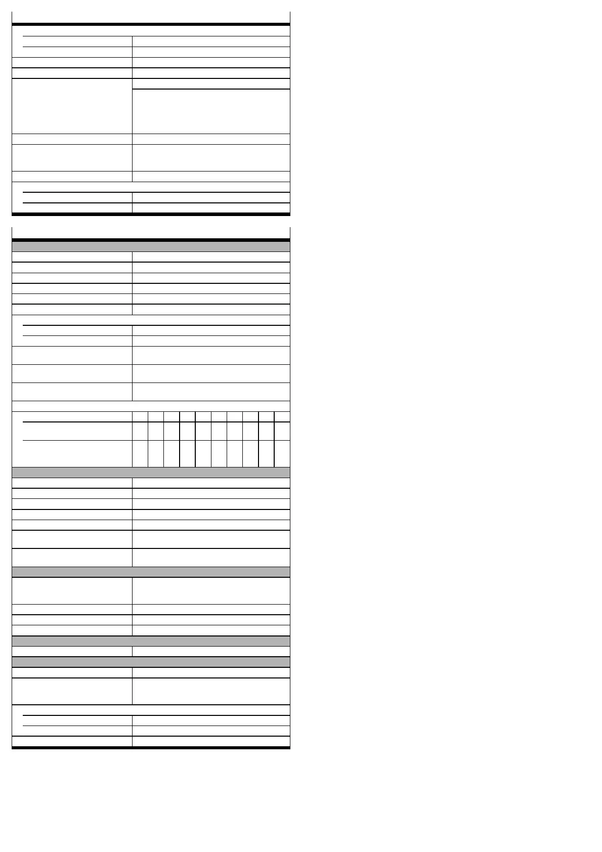
Switch-off time to power output stage inactive and maximum tolerance time for test impulse
Input voltage (STO-A/B) [V] 19 20 21 22 23 24 25 26 27 28
Typical switch-off time
(STO-A/B_OFF)
[ms] 4.0 4.5 5.0 6.0 6.5 7.0 7.5 8.0 8.5 9.5
Maximum tolerance time
for test impulse at 24 V
signal
[ms] <2.0 <2.0 2.0 2.5 3.0 3.5 4.5 5.0 5.5 6.0
Feedb ack contact C1, C2
Design Relay contact, normally open
Max. voltage [V DC] < 30 (ov ervoltage-proof up to DC 60 V)
Nominal current [mA] < 200 (not short-circuit proof)
Voltage drop [V] ≤ 1
Residual current (contact o pen) [µA] < 10
Switching time closing
(T_C1/C2_ON)
[ms] < (STO-A/B_OFF + 5 ms)
Switching time opening
(T_C1/C2_OFF)
[ms] < (STO-A/B_ON + 5 ms)
Auxiliary supply 24V, 0V – o utput
Design Logic power supply o f the motor controller. Protected
against reverse polarity, ov ervo ltage-proof up
to DC 60 V
Nominal voltage [V] 24
Nominal current [mA] 100 (short-circuit proof, max 300 mA)
Voltage drop [V] ≤ 1 (for nominal current)
Galvanic isolation
Galvanically isolated potential areas STO-A / 0V-A; STO-B / 0V-B; C1 / C2; 24V / 0V
Cabling
Max. cable length [m] 30
Screening When wiring outside the control cabinet, use screened
cable. Guide screening into the control cabinet /
attach to the side of the control cabinet.
Cable cross section (flexible conductors, wire end sleeve with insulating collar)
One conductor mm² 0.25 … 0.5
Two conductors mm² 2 x 0.25 (with twin wire end sleeves)
Tightening torque M2 [Nm] 0.22 … 0.25
 Loading...


