2 Product Overview
16 Festo – GDCP-CMMS-AS-G2-HW-EN – 1310NH – English
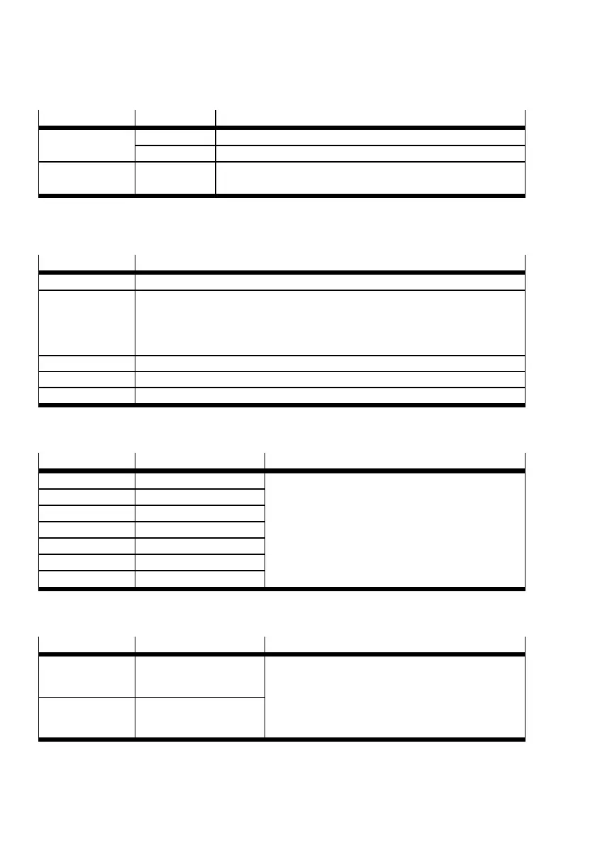
2.4.2 LED displays
LED
LED colour Function
Ready Green Operating status/controller enable
Flashing green Parameter file xxx.DCO (memory c ard) is being red/written
CAN Yellow CAN bus status display illuminates when CAN communication is
taking place
Tab. 2.3 LED status display ( Fig. 2.2 1 )
2.4.3 DIP switches
DIP switch
Function
S1.1 … 7 CAN bus address or MAC-ID Example Tab. 2.5
S1.8 Automatic loading of a new firmware file from the memory card by the start
programme (bootloader):
1)
– ON: Download from the SD memory card to the controller
– OFF: No download.
S1.9 … 10 Setting the CAN-bus transmission rate Example Tab. 2.6
S1.11 Activation of the CAN-bus interface
S1.12 Terminating resistor for CAN-bus
1) For additional information regarding the firmware download Functional description GDCP-CMMS-AS-G2-FW-...
Tab. 2.4 Function of the DIP switches ( Fig. 2.2 3 )
S1.1 … 7
ON/OFF (ex ample) Significance
1)
1 ON 1 DIP switch S1.1 is the low-order bit.
Example: address = 1011011 =91
2 ON 1
3 OFF 0
4 ON 1
5 ON 1
6 OFF 0
7 ON 1
1) Additional information Functional description G DCP - CMMS-AS-G2-FW-...: fieldbus configuration.
Tab. 2.5 CAN bus address or MAC-ID
S1.9 … 10
ON/OFF (ex ample) Significance
1)
9 ON 1 DIP switch S1.9 is the low-order bit.
00: 125 kBit/s
01: 250 kBit/s (example)
10: 500 kBit/s
11: 1000 kBit/s
10 OFF 0
1) Additional information Functional description G DCP - CMMS-AS-G2-FW-...: fieldbus configuration.
Tab. 2.6 CAN-Bus transmission rate

 Loading...


