4 Electrical installation
Festo – GDCP-CMMS-AS-G2-HW-EN – 1310NH – English 41
4.9. 3 Connection to the supply voltage
• Before establishing the connection make sure the power supply is switched off.
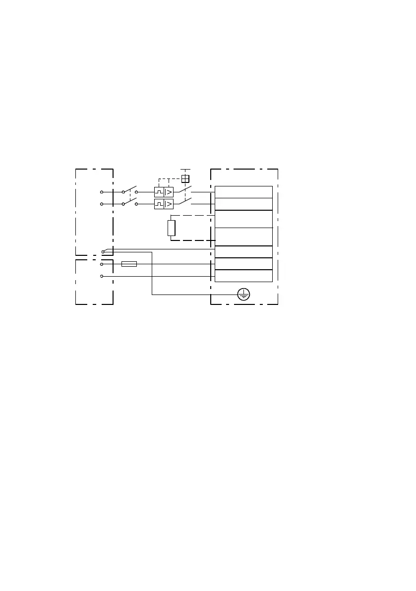
• Before commissioning, and also for brief measuring a nd test purposes, connect the PE protective
conductor Fig. 4.4:
– to the ear thing screw of the controller housing
– to pin PE [X9 .5], power supply.
The cross section of the protective conductor at PE [X9.5 ] must correspond at least to the cross
section of the external c onductor L [X9.1] .
0V
PE
BR-CH
ZK+
L
N
+24 V
GND 24 V
L
N
Q1
[X9]
PE
+24 V
1
2
3
4
PE
1 Mains voltage 95 ... 250 V AC
2 24 V power pack
3 External braking resistor
4 Fuse Chapter A.2.1
Fig. 4.4 Connection to t he supply voltage

 Loading...


