CODESYS libraries and plug-ins
Various libraries and plug-ins for CODESYSV3 are available for the easy actuation
and visualisation of CPX-E modules.
Web server
The integrated web server provides read access to the key parameters and dia-
gnostic functions of the automation system CPX-E. The web server can be
accessed by entering the IP address in the address bar of a web browser.
Factory settings for the web server:
IP address: 192.168.0.1, subnet mask: 255.255.255.0
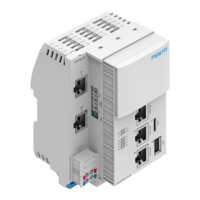
5.2 Configuration
5.2.1 Product design
1
Cover
2
Ethernet network connection
[ETH 1]
3
Memory card slot [Card]
4
USB interface [USB]
5
EtherCAT Master network connec-
tion [EC]
6
Ethernet network connection
[ETH 2]
7
LED indicators
8
Terminal strip for operating
voltage supply U
EL/SEN
[XD]
9
Terminal strip interlock
10
EtherNet/IP network connection
Port 2 [XF2]
11
Linking element
12
EtherNet/IP network connection
Port 1 [XF1]
13
Rotary switch for setting the 4th
octet of the IP address for the
EtherNet/IP network connection
Fig. 1 Product design
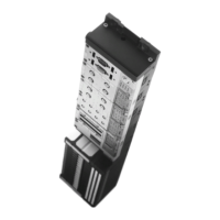
5.2.2 Display components
1
Module-specific LED indicators:
– Operation [Run] (green)
– EtherCAT connection/data
traffic [LA EC] (green)
– Ethernet connection/data traffic
[LA ETH1], [LA ETH2] (green)
2
System-specific LED indicators:
– Operating voltage supply
U
EL/SEN
[PS] (green)
– Load voltage supply U
OUT
[PL]
(green)
– System error [SF] (red)
– Force mode [M] (yellow)
3
Network-specific LED indicators
(EtherNet/IP):
– Module status [MS] (green, red,
orange)
– Network status [NS] (green, red,
orange)
– Connection/data traffic [XF1],
[XF2] (green)
Fig. 2 LED indicators
The module- and network-specific LED displays are described below
è 11.3 LED indicators.
The system-specific LED indicators are described in the documents for the auto-
mation system CPX-E è 1.1 Further applicable documents.
5.2.3 Control elements
5.2.3.1 Run/stop switch
The run/stop switch (DIL switch) is located under the cover.
1
DIL switch (for run/stop)
2
DIL switch (reserved)
Fig. 3 Run/stop switch
NOTICE!
Damage to internal electronics.
Damage to at-risk components due to electrostatic discharge.
• Ensure your body is electrostatically discharged before activating the
run/stop switch.
• Activate run/stop switch as required.
Switch status Function
Run (standard setting) A project can be started using CODESYS (run mode active).
A CODESYS boot application can be started.
Stop A project cannot be started using CODESYS.
A CODESYS boot application cannot be started.
RunèStop A project that is running will be stopped.
StopèRun A project that was stopped using the run/stop switch will be contin-
ued.
Tab. 4 Run/stop switch
5.2.3.2 Rotary switch
NOTICE!
Damage to internal electronics.
Damage to at-risk components due to electrostatic discharge.
• Ensure your body is electrostatically discharged before activating the rotary
switch.
• Activate rotary switch as required.
Rotary switch Function
The 3rotary switches are used to set the 4thoctet of the IP address
for the EtherNet/IP network connection: 192.168.1.XXX.
Possible settings
0 = use the internal configuration (factory setting)
1…254 = Permissible address range
999 = reset to factory setting
For invalid values, the internal configuration is used.
Factory setting
192.168.1.1 (DHCP active)
The DIL switches are reserved and have no function.
Tab. 5 Rotary switch
Changes to the rotary switches only take effect following a restart of the module.
5.2.3.3 Operator unit CDSB (optional)
The operator unit CDSB is available as an accessory
èwww.festo.com/catalogue.
The functions of the operator unit are described in the “Description of controller
CPX-E-CEC-...-EP” è 1.1 Further applicable documents.
5.2.4 Connecting components
5.2.4.1 Operating voltage supply
Port [XD]
1)
Signal
0
1
+24VDC operating voltage supply U
EL/SEN
2
3
0VDC operating voltage supply U
EL/SEN
1) The ports XD.0 and XD.1 and also XD.2 and XD.3, respectively, are interconnected in the terminal strip.
Tab. 6 Port [XD]