Do you have a question about the Festo CPX-E-CEC Series and is the answer not in the manual?
Lists related documentation for the automation system CPX-E.
Defines the qualified personnel for whom this document is intended.
Details the product versions covered by this document.
Explains the components and information on the product label.
Lists the technical standards the product adheres to.
Provides an overview of the controller's purpose, programming, and communication methods.
Explains how inputs and outputs are assigned addresses within the automation system.
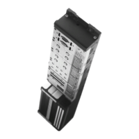
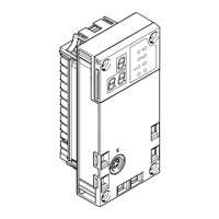
Identifies and labels the physical components of the controller module.
Details the module-specific and system-specific LED indicators.
Describes the physical controls on the module, such as the run/stop switch.
Explains how to connect the power supply to the module.
Details the Ethernet and EtherCAT network connection configurations.
Covers features like FTP server, web server, temperature sensor, and real-time clock.
Describes how system status and errors are displayed via LED indicators.
Explains information displayed via module-specific LEDs.
Details diagnostics through Festo software on a PC.
Covers diagnostics via the EtherCAT network and control software.
Explains diagnostics accessed through the web server.
Describes requesting diagnostic information from devices using SDO access.
Explains how to display recent diagnostic messages via object 0x10F3.
Details the structure of the diagnostics history object 0x10F3.
Explains the individual values within a sample diagnostic message.
Details how emergency messages are activated and deactivated.
Lists error codes and their explanations in the emergency message.
Explains the meaning of bits in the error register (byte 2).
Defines the meaning of status bits in the emergency message.
Explains the CPX module number and CPX error number.
Provides details on additional error information in the emergency message.
Shows the terminal view and lists installed modules with their status.
Displays input and output image data for the connected modules.
Covers terminal, system, and CI interface aspects for parameterisation.
Details system information and CODESYS licence for parameterisation.
Lists system parameters for filter alarm, monitoring, and data format.
Covers parameters for trace data, filters, error reporting, and system bus.
Provides general technical specifications like dimensions, weight, and ambient conditions.
Lists the module codes and identification for different CPX-E-CEC versions.
Details operating voltage, current consumption, and buffering time.
Details network protocol, transmission rate, and cable specifications.
| Operating voltage | 24 V DC |
|---|---|
| Protection class | IP20 |
| Number of ports | 2 |
| Power supply voltage | 24 V DC |
| Category | Controller |
| Fieldbus interface | EtherCAT |
| Communication | EtherCAT |