Do you have a question about the Festo CPX-CEC-C1-V3 and is the answer not in the manual?
Specifies the intended application for the Codesys controller CPX-CEC-...-V3.
Details safety precautions for preventing injury from actuator movements and pressurised lines.
Identifies the intended audience for this manual, requiring automation technology experience.
Provides contact information for Festo service and data required for support queries.
Explains danger categories, pictograms, and text markings used in the document.
Defines pictograms and text markings used for conveying special information.
Lists the software versions covered and related documentation.
Details the variants and common features of the CPX-CEC-...-V3 controller.
Introduces the CODESYS V3 pbF software for commissioning and programming the controller.
Explains the necessity of the associated CPX-CEC package for CODESYS V3 pbF.
Details the memory allocation for global, flash, flag, input, and output memory.
Explains the use and limitations of remanent variables for data storage.
Lists available libraries for simplifying programming with function blocks, declarations, and visualizations.
Describes the different operating modes: Standalone, Remote Controller Ethernet, and Fieldbus.
Details the standalone operating mode with a diagram of the CPX-CEC-...-V3 and terminal.
Explains the Ethernet-based remote controller mode with a system diagram.
Describes the fieldbus-based remote controller mode, requiring a fieldbus node.
Provides general safety precautions and notes for installing the CPX terminal.
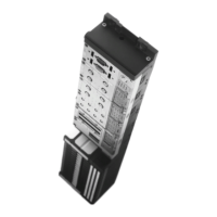
Details the procedure for mounting and removing the CPX-CEC-...-V3 from its sub-base.
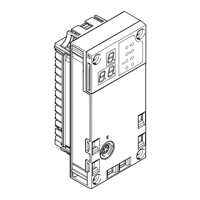
Identifies and describes the various connection interfaces and display elements on the CPX-CEC module.
Explains how to configure the RUN/STOP rotary switch and DIL switches.
Covers the different communication interfaces available on the CPX-CEC controller.
Guides on connecting the CDPX display unit via Ethernet for monitoring automation tasks.
Details connecting the handheld CPX-MMI for commissioning, diagnosis, and parameterization.
Explains how to seal unused sockets and switches with covers for IP65/IP67 protection.
Provides safety warnings and notes for the commissioning process.
Lists the hardware and software requirements for commissioning the CPX-CEC controller.
Outlines necessary preparations, including administrator rights and software installation.
Guides on launching Codesys and creating a new project for the CPX-CEC controller.
Details how to launch and use the 'Scan Festo Devices' program.
Guides on configuring the CPX system by entering order code, automatic scanning, or manual setup.
Details system settings for the CPX terminal, including system and trace parameters.
Guides on parameterizing individual CPX modules, noting that changes are offline.
Explains reading and modifying CPX terminal parameters using a handheld CPX-MMI.
Details the rotary switch function and its assignment to a variable for controller state.
Guides on configuring CANopen slaves, including setting baud rates and adding devices.
Covers configuration for SoftMotion, supporting coordinated multi-axis movements.
Explains how to configure the controller for Modbus TCP Client and Master operations.
Explains how to establish an online connection (login) with the CPX-CEC controller.
Explains how to manipulate input and output signals for testing purposes.
Introduces the PLC shell for controller monitoring, diagnostics, and debugging.
Describes how the controller behaves when errors occur and general diagnostic options.
Explains the meaning of the status LEDs on the CPX-CEC module.
Guides on performing online diagnosis within the controller configuration.
Details error output points and diagnostic information within SoftMotion.
Explains how to access diagnostic information via the web server using the 'Homepage' function.
Lists Festo libraries for performing diagnosis within the user program.
Mentions the availability of the CAA_CiA405.Library for diagnosing CANopen modules.
Explains the task-dependent I/O update mechanism and how to manage pointers.
Details how to use the CANopen_Manager, including starting slaves simultaneously.
Explains node guarding telegrams and updating I/O while in stop mode.
Notes that CPX-MMI parameters are overwritten by Codesys project parameters.
Addresses messages for incompatible runtime data and controller software.
Provides general technical data for the CPX terminal and its variants.
| Product Type | Controller |
|---|---|
| Communication Protocol | PROFINET |
| Nominal Operating Voltage DC | 24 V |
| Max. Output Current Per Channel | 0.5 A |
| Max. Total Output Current | 4 A |
| Electrical Isolation | Yes |
| Number of Digital Inputs | 16 |
| Number of Digital Outputs | 16 |
| Digital Output, Short-Circuit Proof | Yes |
| Digital Output, Overload Proof | Yes |
| Digital Output, Polarity Reversal Protection | Yes |
| Switch-On Delay of Outputs | 1 ms |
| Switch-Off Delay of Outputs | 1 ms |
| PWM Frequency | 1 kHz |
| Cycle Time | 1 ms |
| Parameter Channel | Yes |
| Diagnostic Channel | Yes |
| PROFINET Cycle Time | 1 ms |
| PROFINET IO Device | Yes |
| PROFINET MRP | Yes |
| PROFINET Shared Device | Yes |
| Web Server | Yes |
| Number of Ethernet Ports | 2 |
| Ethernet | 10/100 Mbps |
| Port Type | RJ45 |
| Switch Functionality | Yes |
| Transmission Rate | 10/100 Mbps |
| Protocol | TCP/IP |
| Memory Card Slot | Yes |
| Real-Time Clock | Yes |
| Diagnostic Display | LED |
| Type of Mounting | DIN rail |
| Mounting Position | Any |
| Degree of Protection | IP20 |
| LABS (PWIS) Conformity | Yes |
| Note on Materials | RoHS compliant |
| Number of Ports | 2 |
| Operating Voltage Range DC | 18 V ... 30 V |
| Digital Inputs According to | IEC 61131-2 |
| Digital Input Voltage Range | 0 - 30 V |
| PROFINET Standard | IEC 61158 |
| PROFINET Protocol | RT |
| Function | PLC |
| PLC Cycle Time | 1 ms |
| Operating Temperature | 0 °C to 50 °C |
| Storage Temperature | -20 °C ... 70 °C |
| Relative Air Humidity | 5% to 95% (non-condensing) |
| Vibration Resistance | 5 g |
| Shock Resistance | 15 g |
| Corrosion Resistance Class CRC | CRC 2 |
| Digital Input Current | 3 mA |