Festo control block CPX-CEC
3.5 Interfaces
3.5.1 Ethernet interface
The Ethernet interface enables a programming device, PC or operator unit to be connected to the Codesys
controller.
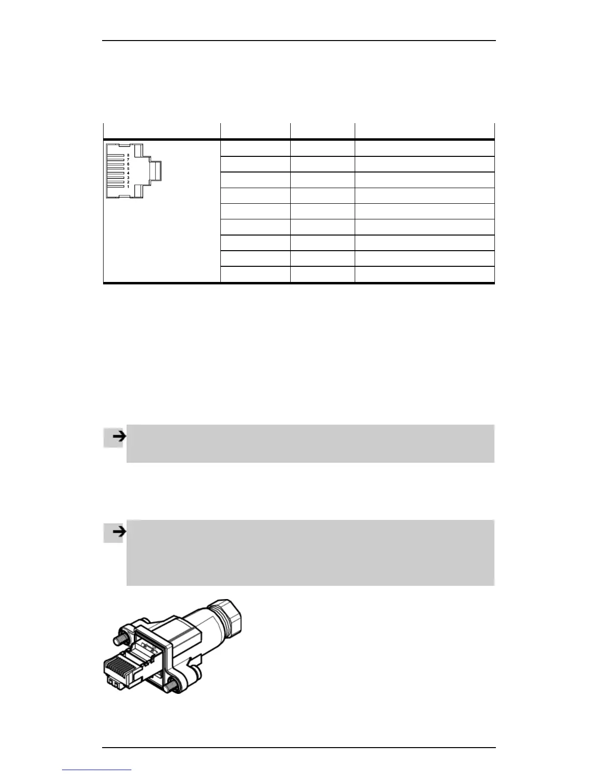
The Ethernet interface is designed as an RJ45 socket.
Socket Pin Signal Comment
1
TD+
Transmitted data+
2
TD–
Transmitted data–
3
RD+
Received data+
4 n.c. Not connected
5 n.c. Not connected
6
RD–
Received data–
7 n.c. Not connected
8 n.c. Not connected
Housing
Screen
Screen
Table: Pin allocation of the Ethernet interface
If the Ethernet interface is not used, seal it with a cover AK-RJ45. This provides protection to IP65/IP67
( section Ensuring protection to IP65/IP67).
Ethernet cable
Use connecting cables with the following specification:
– Screened flexible Ethernet round cable from category 5
– Max. outside diameter: 5.4 mm
– Core diameter: 0.89 ... 1.0 mm AWG24-26
– Assembly: Via crimp tool to RJ45
must be provided with strain relief.
Network connection
You will need a patch or crossover cable to connect your Codesys controller to a network or PC. The
interface automatically detects which cable is connected and automatically switches the signals.
Note
• Use the RJ45 plug from Festo to ensure protection to IP65/IP67 ( section Ensuring protection
to IP65/IP67):
– FBS-RJ45-8-GS
• Refer to the fitting instructions for the plug.
Figure: RJ45 plug FBS-RJ45-8-GS
14

 Loading...