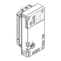
2.3 Product design
1
LED indicators
2
DIL switch
3
Terminal strip for operating voltage supply U
EL/SEN
[XD]
4
Terminal strip interlock
5
Network connection (EtherCAT) [EC]
6
Linking element
7
Network connection (Ethernet) [ETH]
Fig. 2 Product design
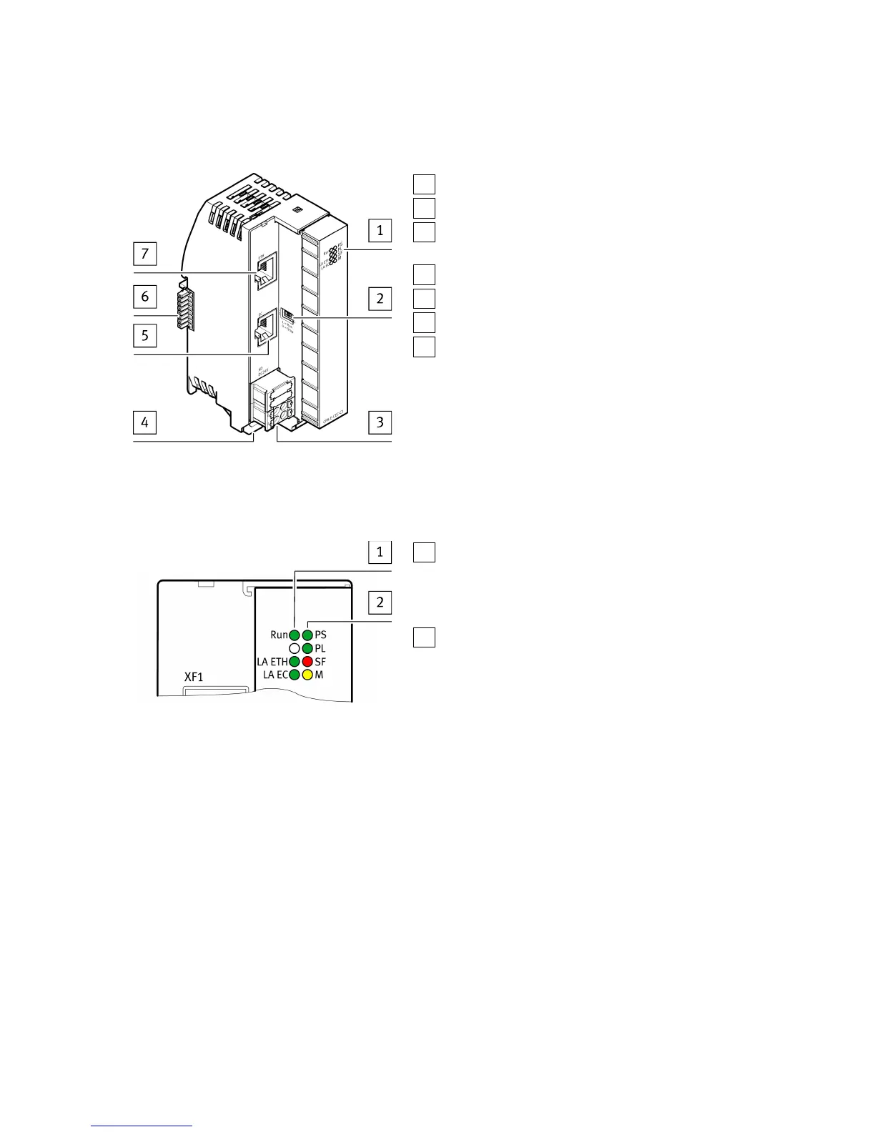
2.4 Display components
1
Module-specific LED indicators:
– Operation [Run] (green)
– Connection/data traffic Ethernet [LA ETH] (green)
– EtherCAT connection/data traffic [LA EC] (green)
2
System-specific LED indicators:
– Operating voltage supply U
EL/SEN
[PS] (green)
– Load voltage supply U
OUT
[PL] (green)
– System error [SF] (red)
– Force mode [M] (yellow)
Fig. 3 LED indicators
Function
7Festo — CPX-E-CEC-... — 2018-09