2.5 Control elements
2.5.1 Run/stop switch
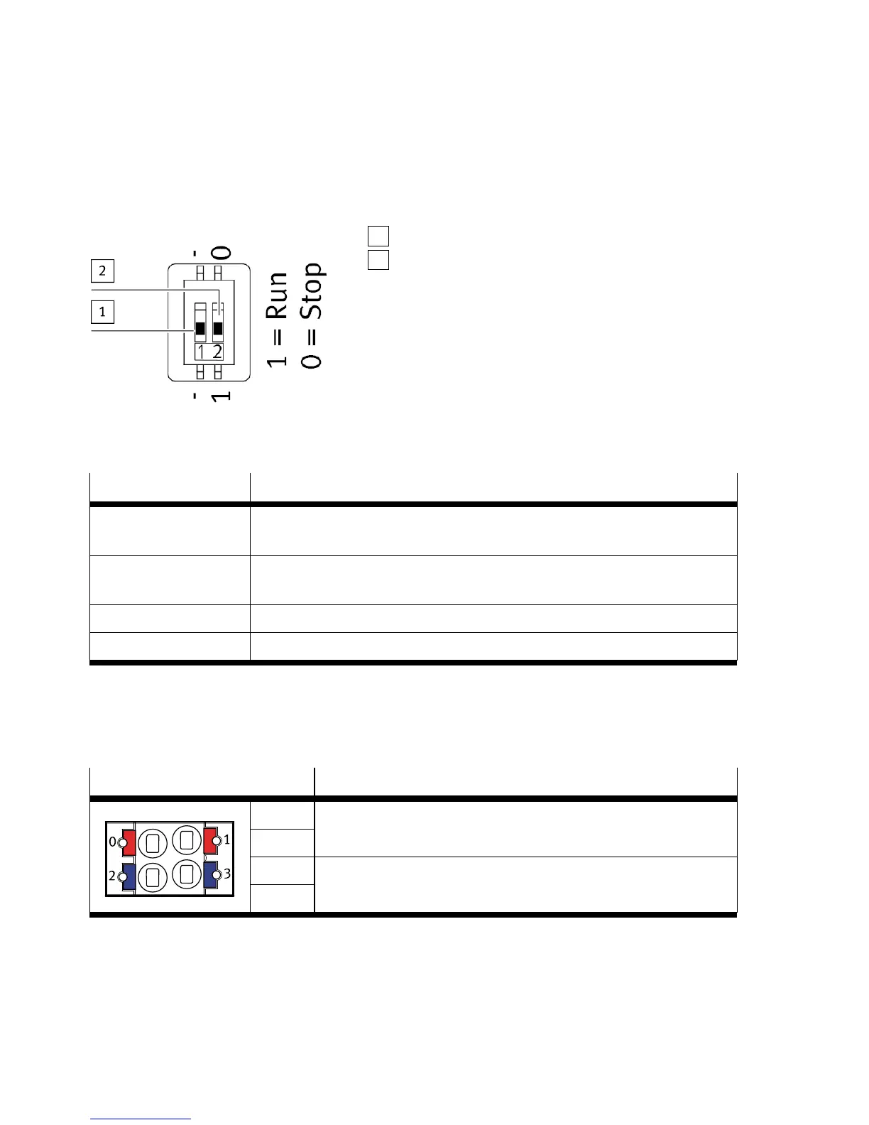
The run/stop switch (DIL switch) is located on the left side of the module.
1
DIL switch (reserved)
2
DIL switch (for run/stop)
Fig. 4 Run/stop switch
Switch status Function
Run (standard setting) A project can be started using CODESYS (run mode active).
A CODESYS boot application can be started.
Stop A project cannot be started using CODESYS.
A CODESYS boot application cannot be started.
RunèStop A project that is running will be stopped.
StopèRun A project that was stopped using the run/stop switch will be continued.
Tab. 5 Run/stop switch
2.6 Connecting components
2.6.1 Operating voltage supply
Port [XD]
1)
Signal
0
1
+24VDC operating voltage supply U
EL/SEN
2
3
0VDC operating voltage supply U
EL/SEN
1) The ports XD.0 and XD.1 and also XD.2 and XD.3 are interconnected in the terminal strip.
Tab. 6 Operating voltage supply
Function
8 Festo — CPX-E-CEC-... — 2018-09