Requirements
– PC (Windows7 and later) with Ethernet interface
– Components for network connection
– Programming software CODESYSV3
– Package CPX-E-CEC compliant with firmware of product
Preparations
The user requires administrator rights to install and operate programming soft-
wareCODESYSV3.
1. Install CODESYSV3.
2. Start CODESYSV3 with administrator rights.
3. Open Package Manager èmenu command [Tools] [Package Manager].
4. Install the current package for CPX-E-CECè online help for CODESYSV3
è“Package Manager”.
5. Restart CODESYSV3 in order to use the new package.
6. Connect the controller to the network connection[ETH 1] or [ETH 2] through a
switch/hub or directly to the PC è 8.1 Network.
7. Adapt the network settings èmenu command [Online] [Scan Festo Devices]
èonline help for CODESYSV3 è“Scan Festo Devices”.
The current version of the packageCPX-E-CEC for CODESYSV3 is available in the
Festo Support Portal èwww.festo.com/sp.
Further information is available in the product-specific Help
èOnline help for CODESYSV3 è“Getting started”.
Procedure for unwanted program states
If a program with real-time priority is not responding:
1. Set run/stop switch to stop.
Ä
The boot application cannot be started.
2. Restart the controller.
3. Establish connection to CPX-E-CEC.
4. Delete boot application using “Reset device to original state”
èGeneral help for CODESYSV3.
10 Service
NOTICE!
Accumulation of heat due to reduced air supply to electronics.
• Keep the ventilation slots free and regularly remove contamination.
10.1 Firmware service (update)
• Update the controller firmware with suitable software from Festo
èwww.festo.com/sp.
11 Diagnostics and fault clearance
11.1 Diagnostics options
Various options are available for diagnosing errors:
– Internal system diagnostics
– LED indicators on the product
11.2 Internal system diagnostics
The internal system diagnostics is described in the “Description of automation
system CPX-E” è 1.1 Further applicable documents.
11.3 LED indicators
The module- and network-specific LED displays are described below.
The system-specific LED indicators are described in the documents for the auto-
mation system CPX-E è 1.1 Further applicable documents.
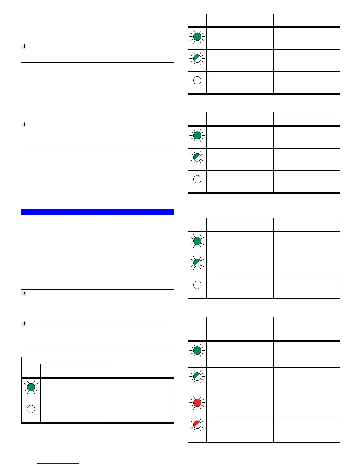
Module-specific LED indicators
Operation [Run]
LED
(green)
Meaning Remedy
Lit
CODESYS application is running –
Off
CODESYS application is not available or
has stopped
–
Tab. 11 Operation [Run]
Ethernet interfaces [LA ETH 1] [LA ETH 2]
LED
(green)
Meaning Remedy
Lit
Network connection established
Status “Link”
–
Flashing
Network connection established
Status “Activity”
–
Off
No network connection Check network connection.
Tab. 12 Ethernet interfaces [LA ETH 1] [LA ETH 2]
EtherCAT interface [LA EC]
LED
(green)
Meaning Remedy
Lit
Network connection established
Status “Link”
–
Flashing
Network connection established
Status “Activity”
–
Off
No network connection Check network connection.
Tab. 13 EtherCAT interface [LA EC]
Network-specific LED indicators
Connection status [XF1], [XF2]
LED
(green)
Meaning Remedy
Lit
Network connection established
Status “Link”
–
Flashing
Network connection established
Status “Activity”
–
Off
No network connection Check network connection.
Tab. 14 Connection status [XF1], [XF2]
Module status [MS]
LED
(green,
red,
orange)
Meaning Remedy
Lit up
green
Normal operating status –
Flashing
green
Configuration of automation system CPX-E
not complete or not correct
Complete or correct configuration of the
automation system CPX-E.
Lit up red
Error cannot be rectified Contact Festo Service èwww.festo.com.
Flashing
red
Error can be rectified Check configuration of the automation
system CPX-E.